The Deta Grid Connect Smart Double Gang Touch Light Switch (6912HA) is a $60 AUD Australian smart wall switch built around a BK7231T Tuya chip.
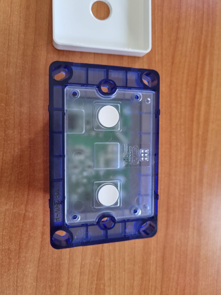
Removing the faceplate and four cover screws exposes the PCB, which can be pulled out for flashing after inserting a 5-pin header strip into the pin holes.
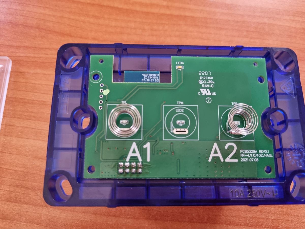
The header pins map top to bottom as 3.3V, TXD1, RXD1, TXD2, and Ground, with OpenBK7231T flashing triggered through the WB3S CEN pin.
OpenBK7231T booted normally, WiFi configuration succeeded, and the relay, button, and WiFi LED pins were assigned as P6, P9, P14, P24, and P26.
Prying the PCB out requires care because the contact bins in the lower left can bend, and the ground harness on the chip is optional.
Generated by the language model.
This is a short teardown of the Deta Grid Connect Smart Double Gang Touch Light Switch (6912HA). It is sold in Australia and costs approximately $60 AUD from Bunnings.
The switch uses a BK7231T Tuya chip.
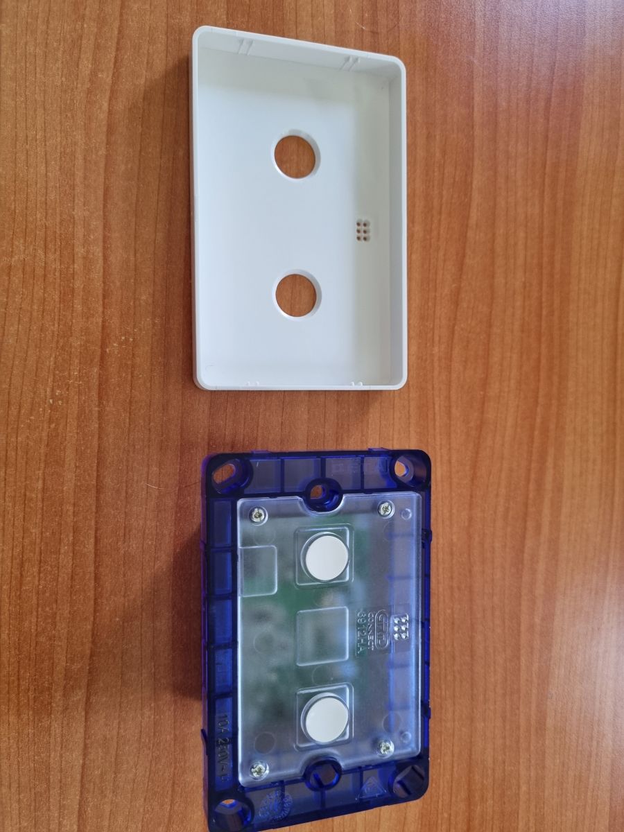
Pull off the faceplate and remove the cover by unscrewing the four screws shown. A tool is useful to pry away the cover.
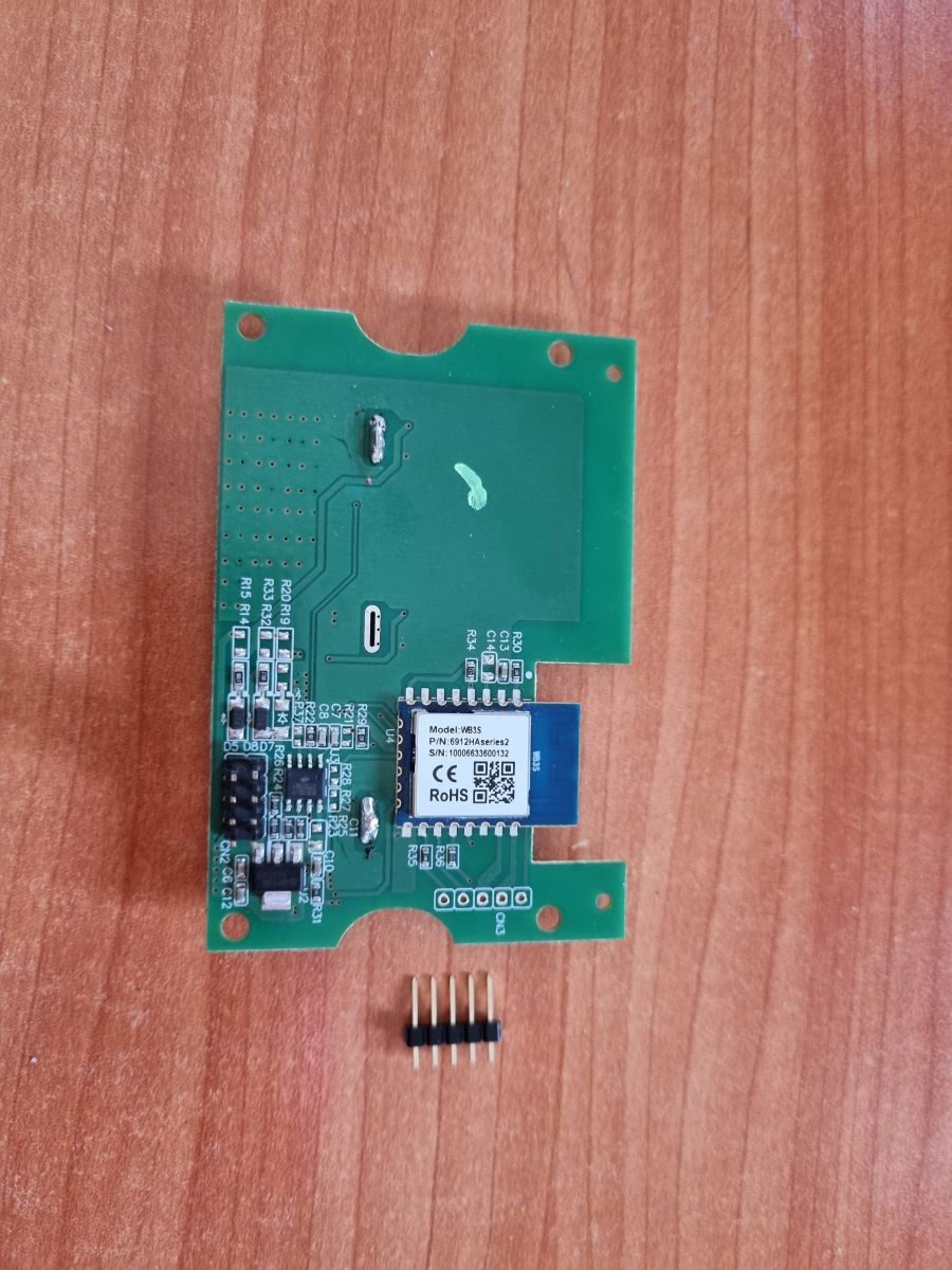
Delicately pull out the PCB, being careful not to bend the contact bins in the lower left-hand side. A tool such as a knife is useful to do this.
Installing OpenBK7231T:
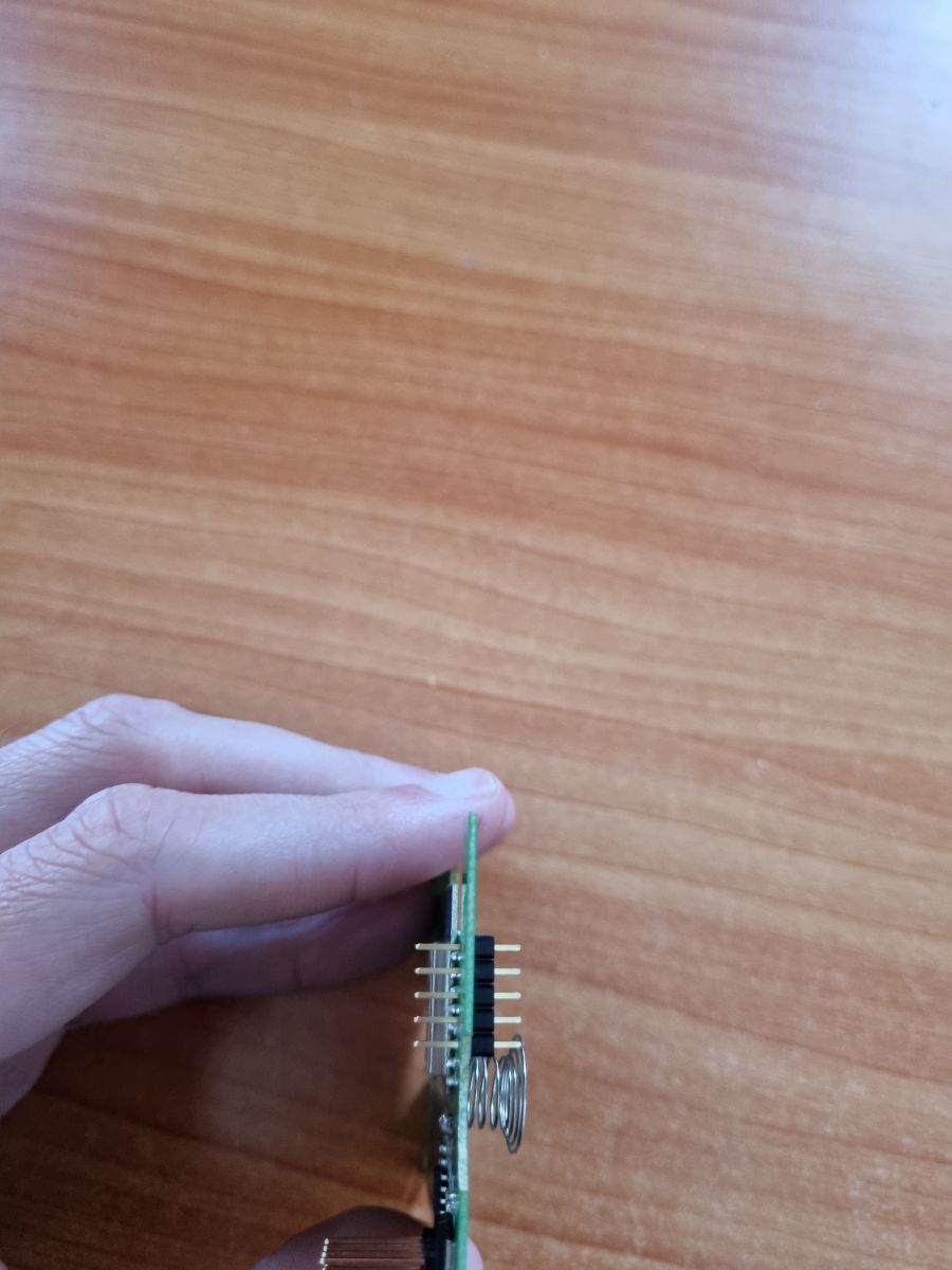
I inserted a 5-pin header terminal strip into the pin holes shown. From top to bottom (with the WB3S chip shown upright in the top right corner of the PCB) these correspond to:
1. 3.3V
2. TXD1
3. RXD1
4. TXD2
5. Ground
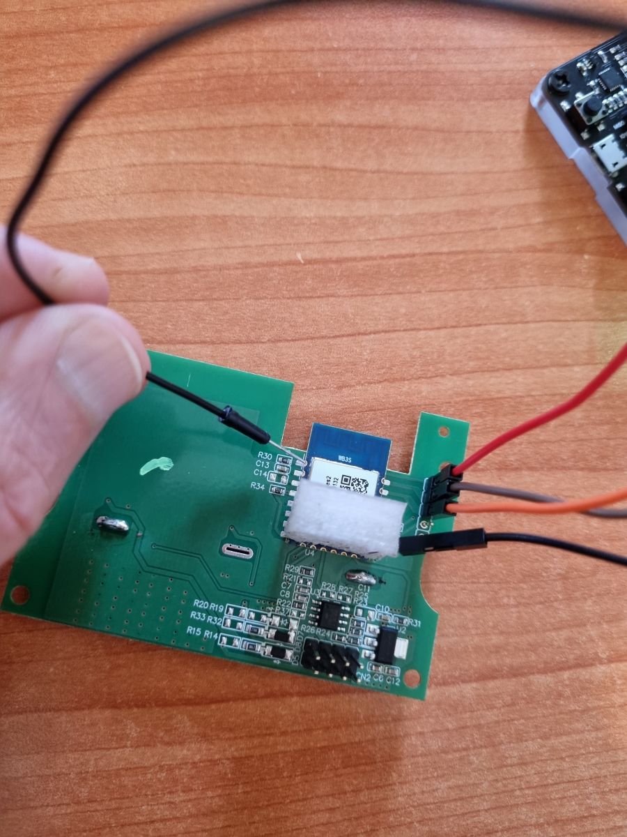
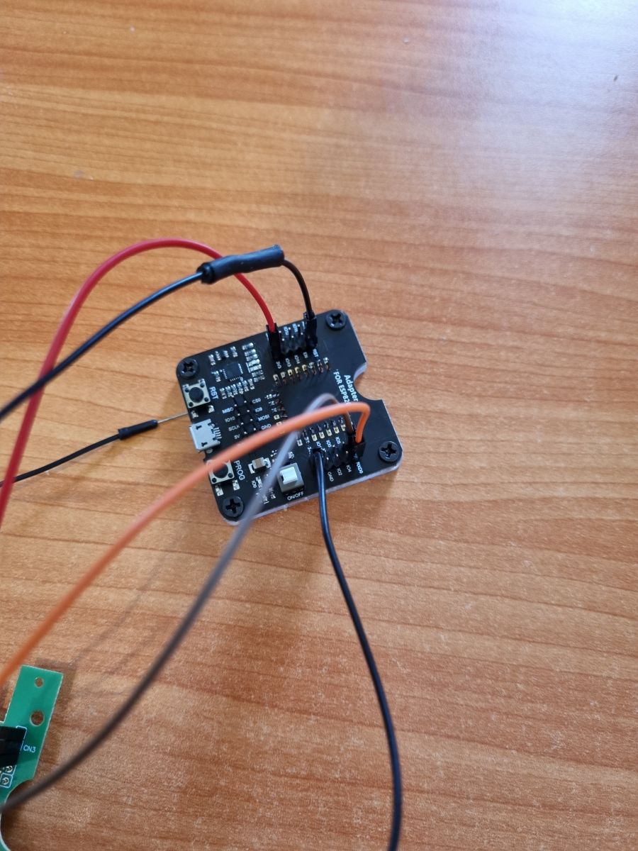
I connected 1-3 via female Dupont wires to the corresponding pins on an ESP flashing tool. I inserted a jig/harness on top of the WB3S chip that made direct contact with the ground pin as shown, and connected this also to a ground pin on the flashing tool. The harness is optional; I could also have just soldered it directly to the chip.
Lastly I connected a female Dupont wire to the RESET pin on the flashing tool and made contact with the WB3S CEN pin to trigger flashing mode during the flashing process.
Web App Configuration:
The chip started up fine with no issues. I configured WiFi and added the pin configuration below. This was adapted from Tasmota device information found here.
Thank you for presentation. Btw, isn't the "4.???" pin CEN? Altough I am not sure... [Read more]
binchicken
11 Feb 2023 00:03
p.kaczmarek2 - Apologies about the late reply. My multimeter indicates that pin 4 is TXD2, not CEN. [Read more]
p.kaczmarek2
11 Feb 2023 09:15
That's as I expected. Anyway... everything works correctly, right? If you need any help, just tell me. [Read more]
mattmck
29 Apr 2023 07:41
I've managed to use cloudcutter to pull one of these switches out of the cloud, and I have openbeken installed at the moment.
What's strange is that via Home Assistant or the openbeken web interface... [Read more]
p.kaczmarek2
29 Apr 2023 07:46
It means that software thinks that button is pressed by the user all the time. It may mean that you have chosen wrong GPIO for the button (one that has no button in reality) or that the Tuya is using inversed... [Read more]
mattmck
29 Apr 2023 09:09
Spot on, fixed. The issue was using btn_n incorrectly. No fixed and all is responsive. Thank you. [Read more]
Dernheart
06 May 2023 01:06
Thanks for the fantastic write up. It worked perfectly for me!
A couple of points of interest I found:
- I am wondering why you opted to connect ground directly to the module instead of pin 5? I have... [Read more]
p.kaczmarek2
06 May 2023 07:53
I am using power supply (turn off and on the power) trick all the time and it works very well.
In some cases, while disconnecting the power from WiFi module, I sometimes have to temporarily connect... [Read more]
rohanb
14 Dec 2025 19:17
Hi Everyone
There is a new series 3 version of these that uses a BK7231N
Pins are
"pins": {
"6": "Rel;1",
"8": "WifiLED_n;1",
"14": "Btn;1",
"24": "Btn;2",
"26": "Rel;2"
... [Read more]
My log shows endless “Button_OnLongPressHold”. What’s wrong?
The firmware sees a constant key press. You likely assigned the wrong GPIO role. Use Btn for active-high or Btn_n for active-low inputs [Elektroda, p.kaczmarek2, post #20559698]
What GPIO roles work for OpenBeken on this switch?
Can I power the board from a 5 V-only USB-to-Serial adapter?
No. Feed the module a regulated 3.3 V; use a bench supply if the adapter lacks 3.3 V on VCC [Elektroda, Dernheart, post #20568428] Over-voltage risks permanent damage.
What load can each gang handle?
The retail listing states 240 V AC at 10 A per channel, equal to 2.4 kW resistive load [Bunnings, 2023].
Edge case: why does power cycling sometimes fail to reset the module?
Residual current via RX/TX can latch the BK7231T. Briefly short VDD to GND during the power-off phase, then reconnect VDD and power up [Elektroda, p.kaczmarek2, post #20568518]
Quick 3-step method to flash without soldering CEN
Selecting incorrect button polarity. This causes ghost presses and unreliable toggling until Btn/Btn_n roles match the hardware [Elektroda, p.kaczmarek2, post #20559698]


Comments
Thank you for presentation. Btw, isn't the "4.???" pin CEN? Altough I am not sure... [Read more]
p.kaczmarek2 - Apologies about the late reply. My multimeter indicates that pin 4 is TXD2, not CEN. [Read more]
That's as I expected. Anyway... everything works correctly, right? If you need any help, just tell me. [Read more]
I've managed to use cloudcutter to pull one of these switches out of the cloud, and I have openbeken installed at the moment. What's strange is that via Home Assistant or the openbeken web interface... [Read more]
It means that software thinks that button is pressed by the user all the time. It may mean that you have chosen wrong GPIO for the button (one that has no button in reality) or that the Tuya is using inversed... [Read more]
Spot on, fixed. The issue was using btn_n incorrectly. No fixed and all is responsive. Thank you. [Read more]
Thanks for the fantastic write up. It worked perfectly for me! A couple of points of interest I found: - I am wondering why you opted to connect ground directly to the module instead of pin 5? I have... [Read more]
I am using power supply (turn off and on the power) trick all the time and it works very well. In some cases, while disconnecting the power from WiFi module, I sometimes have to temporarily connect... [Read more]
Hi Everyone There is a new series 3 version of these that uses a BK7231N Pins are "pins": { "6": "Rel;1", "8": "WifiLED_n;1", "14": "Btn;1", "24": "Btn;2", "26": "Rel;2" ... [Read more]