Teardown of
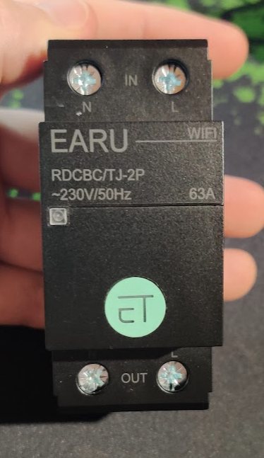
this DIN-rail energy meter from AliExpress.
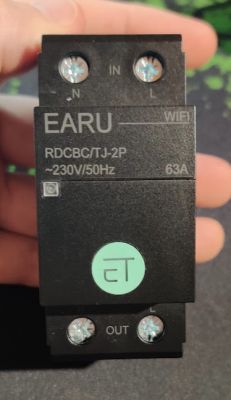
It is branded EARU RDCBC/TJ-2P. It looks cosmetically identical to
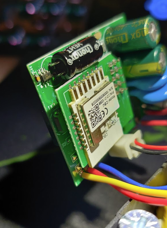
one I bought previously branded VKSELE VKS-2P, but the mainboard and wifi module are completely different. This one has a CBU module, which appears to be an BK7231N, where the VKS-2P was a WB3S (BK7231T).
It's very easy to access; only 2 screws in the back and it just opens right up.
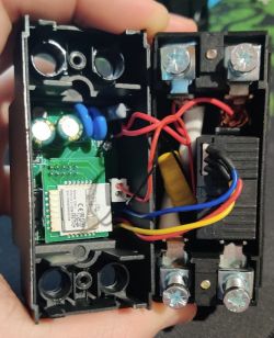
Inside, the mainboard is secured in place with with 2 more small screws, one of them is hidden behind a capacitor which is folded down.
There's a big relay, and a CT for energy measurements. There are no Tuya chips.
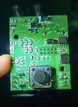
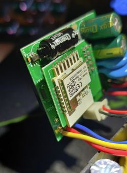
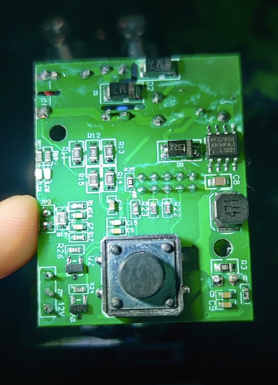
Other side of the board with the button:
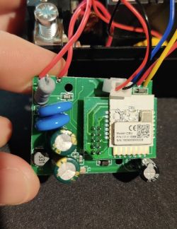
Just like the older device, the CPU board is positioned on a soldered-down riser from the main board, and there is a small 8-pin chip deep under there which I can't see, with pins leading directly to the CPU. My guess is still that it's probably BL0937.
I haven't attempted flashing yet, I haven't seen mention of this CBU in other places, maybe it's fairly new?
I'm assuming it's a BK7231N, and I'll try to follow the procedure for that chip.
I tested the pins connecting the riser to the main board with the continuity meter, and it seems roughly the same pin layout as the VKS-2P I dismantled earlier.
Added after 1 [hours] 42 [minutes]:
I've flashed using the command:
python uartprogram ./OpenBK7231N_QIO_1.15.152.bin --unprotect -d com7 -w --startaddr 0x0
On the first time while it was waiting for connection, I powered on the chip and it continued waiting until it timed out.
On the second try, I ran the program and powered on the device and it spotted it immediately and flashed the software.
I'm trying to configure the device now, but it's not at all like the VKS-2P I had previously.
It seemed the VKS-2P had BL0937 hidden under the wifi board, but I can see on this new model that there is also a chip hidden under the wifi board, but it has 10 pins rather than the 8 on the previous version (BL0937 has 8 pins). So this is something else.
Using a meter I could trace that these pins breakout to the mainboard: P9, P16, P24, P26, P28, TX1, RX1
I found the LED seems to be connected to P28, and button is connected to P26, red led is P9 (it could be power led or wifi led). P24 and P16 toggle the relay; to change state, when one is high, the other must be low, and vice versa.
That leaves no GPIO for the meter, so that must be what TX/RX are for, and it does seems to be a BL0942 chip.
I configured the device like this, which closely matches factory behaviour:
  P9  AlwaysHigh / WifiLED  (if you want the red led to be a power light or a wifi indicator)
  P16 Rel_n
  P24 Rel
  P26 Btn
  P28 LED

  startDriver BL0942

Also to match default firmware:
  +Flag 6
  Startup state: -1
The energy meter is not correct out-of-the-box, and apparently I have to calibrate, which I haven't done yet.


Comments
Hey, BL0942 is using RX and TX lines. Maybe it's a BL0942 version? BL0942 seems like a newer version of BL0937 that uses UART communication. Have you tried "startDriver BL0942"? Regarding relay... there... [Read more]
I worked out the function of all pins now. I also worked out how to control the relay. EDIT: updated OP for future readers clarity It seems to be getting readings that look close-ish, but not correct...... [Read more]
So it's BL0942. That proves it. Now, you need to calibrate it - just like in Tasmota - VoltageSet, CurrentSet and PowerSet commands. With the latest updates, calibration will be saved automatically. Calibration... [Read more]
That's great, there's a heap of extra information there. It looks like it doesn't report power factor, but does the chip provide accurate values to calculate power factor correctly? Can you please read... [Read more]
@turkeyman calibration menu can be done for 100% free cost (in a terms of flash memory size) in a WebApp, and just execute commands in a background. Do you know Javascript? PS: Do you know that... [Read more]
Wouldn't PZEM-004T+ESP be cheaper and with similar parameters? I'm asking because I'd like to find something similar but cheaper. [Read more]