Hi All,
This is my first post, after watching this project over the last few months, and deciding I should give it a go!
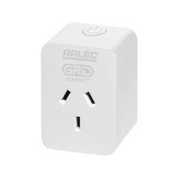
This is a quick teardown of the Arlec Grid Connect PC191 Smart Plug-In Socket with Energy Meter
These are available through Bunnings in Australia
individually for about AU$20 and in an even cheaper
4 pack
TLDR I have also built a Cloudcutter profile for this, so its not necessary to open the unit if you want to flash custom firmware. I've raised a pull request with cloudcutter which hopefully gets merged, but otherwise "tuya-generic-nas-wr01w-smart-plug" has the same profile and so should work as well.
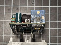
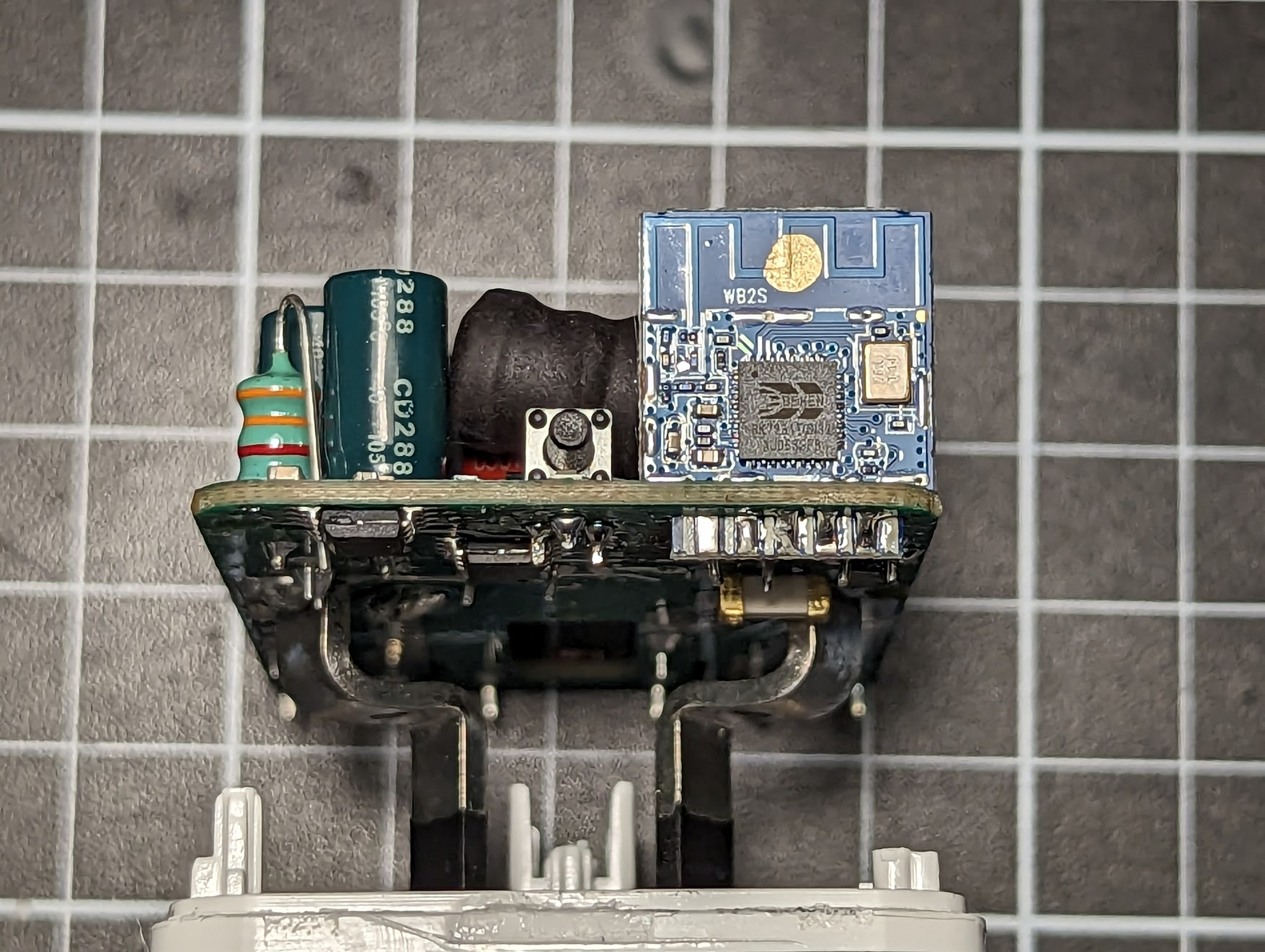
This uses a Tuya WB2S module with a BK7231T chip.
The device itself is fully ultrasonically welded in its plastic case, so not easy to dismantle without damage, however a generous tap with a small set of pliers while working around the seam with a thin, wide spudger was enough to break it free. Once disassembled there are no screws inside and the mains terminals pull through the enclosure. This also means reassembly will need to be strong enough to maintain mains isolation, so don't skimp on the super glue

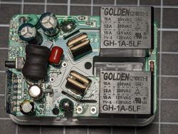
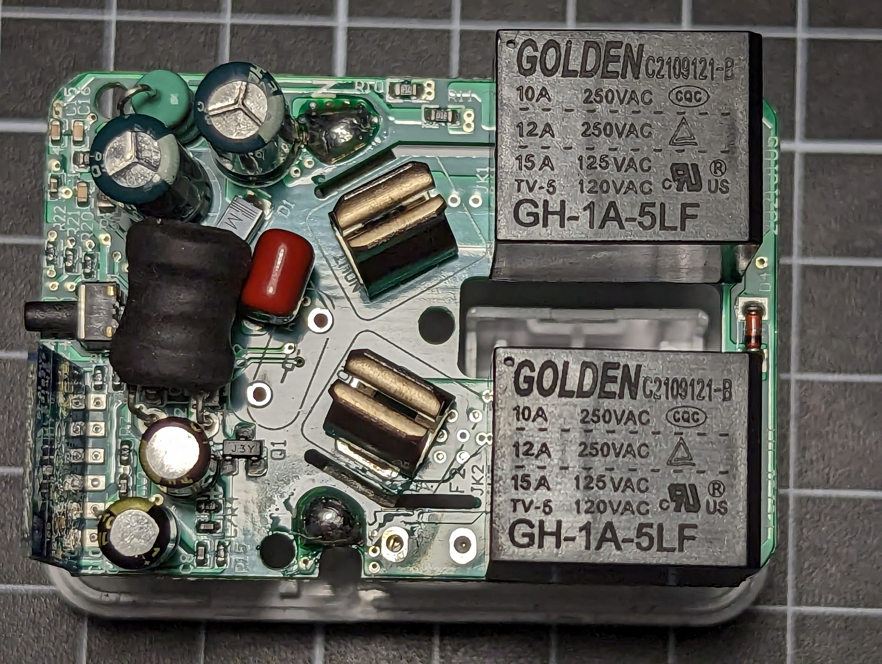
Inside I was relieved to see dual relays for switching active and neutral, though as with most of these devices, there is is a non-isolated power supply for the wifi module, so all IO are live, beware while debugging or flashing.
As the TX/RX pins are used for the LED and Button, Dumping/Flashing also requires removing the module (or at least desoldering the TX/RX pins).

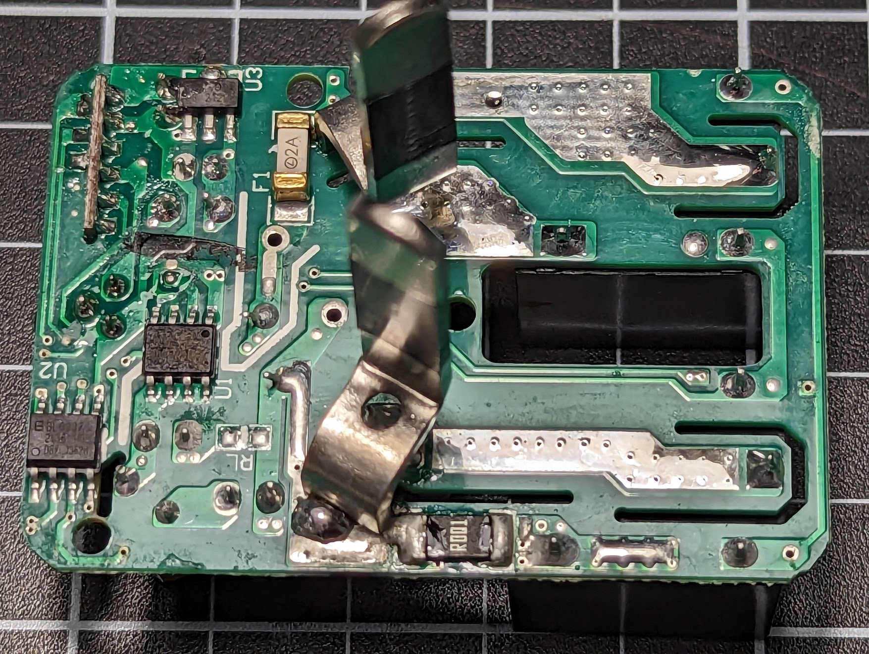
There is one button, a red 'wifi' status LED, a blue relay indicator, a single relay control for both active and neutral relays, and a BL0937 energy meter.
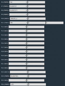
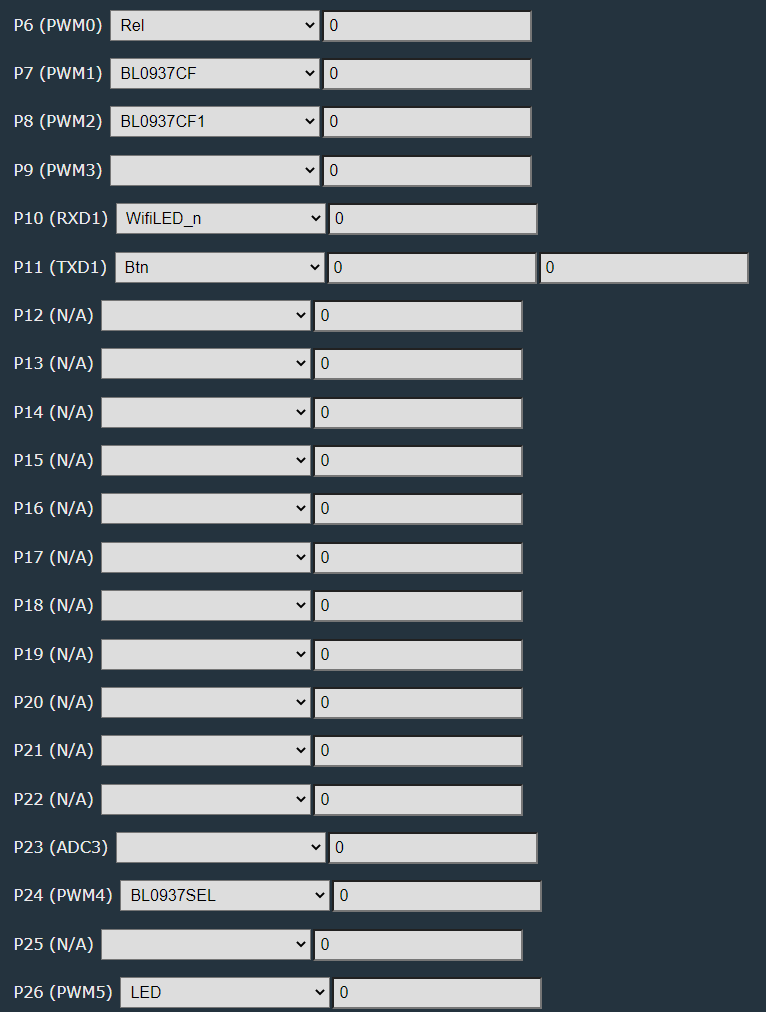
P6 (PWM0) is the Relay
P7 (PWM1) is the BL0937CF pin
P8 (PWM2) is the BL0937CF1 pin
P24 (PWM4) is the BL0939SEL pin
P26 (PWM5) is the LED
P11 (TXD1) is the Button
P10 (RXD1) is the Wifi LED
Safely reassemble it all, and then don't forget to calibrate the BL0937.
I did an unloaded Voltage measurement for
VoltageSet, then hooked up my calibrated multimeter an measured the True RMS current with a large load (2kW heater), then ran
CurrentSet. Note that this does not appear to automatically calculate Power properly, so you should use a resistive load (like a simple radiator heater with no fan), and note that if it is a large load, it will cause voltage in your house wiring to drop, and so it's important to measure the voltage and the current at the same time if possible, to calculate the power.
On one of my units it did seem to calculate the correct power without a
PowerSet command, however on 3 others it did not - I'm not sure why this is, but this may be because the one unit had already paired to Tuya previously, or this may be a red herring?
I also noticed that (on OBK 1.15.241) relay state changes do not update over MQTT if wifi is not connected, for example, if the unit is unplugged while on, then plugged back in, it will not revert the HA state to off once it reconnects to wifi. This also means if you plug in the device and press the physical button to turn the relay on before wifi connects, that state is not reflected.
Comments
Hello, thank you for teardown. This is very informative. Regarding your concern - there is a flag 'broadcast self state on MQTT connect , which in older versions was not set by default. Maybe you... [Read more]
Thanks, I will try the mqtt flag. Although there are 2 relays they can't be independently controlled and are both wired to the same pin on the module so they operate together. One relay switches the... [Read more]
Ah ok, so it explains everything. I assumed too quickly that there are two completely separate relays and overlooked photos. If they must work together, then everything is ok. By the way, it's the first... [Read more]
Good Afternoon, I was able to install firmware to one of these devices today using the cloud cutter method, everything seems to work fine. Thanks for the detailed teardown. I am new to this firmware,... [Read more]
Hello, it's very easy to do this in OpenBeken! We have already a topic about that here: [OpenBeken] Push button actions multi press and hold down etc The sample code for autoexec.bat (from LittleFS... [Read more]
Thanks for your quick reply, I was able to add the event handler rules and now I get MQTT messages, I will read though the links you posted when I get home and try work out the best way to get those events... [Read more]
I tried to flash it but cloudcutter failed to connect to it. What am I doing wrong? Wiping NetworkManager configs Scanning for open Tuya SmartLife AP ... Found access point name: "GRID-CD05", trying... [Read more]
Do you get any access point errors when first starting the cloudcutter script? I personally ended up have to use and wi-pi usb wifi adapter after trying multiple other devices with internal wifi ad... [Read more]
eventually it worked, but I am trying now to find esphome code for it =) [Read more]
Here you can get the latest binaries of our firmware: https://github.com/openshwprojects/OpenBK7231T_App/releases [Read more]
OK... I have ventured into the world I dont yet understand =( I thought it was an easy update =( Created a bin file with ESPHome, it all went well and works without any GPIO pin definitions. But as soon... [Read more]
Sorry I don't know anything about that firmware. As I said, we're using OpenBeken with online builds here. You just go to Releases tab, and get binary, and done. No problems, no compiling, more time... [Read more]
thanks. Learning as I go... If I dont get any readings from the BL0937, does it mean the pins are incorrect? [Read more]
Well, it depends... you should have set the pins and restarted the device, and BL0937 driver should be running. If you still have no data, then indeed, it might be caused by wrong pins selection. Tuya... [Read more]
Are there any UF2 firmware files I can use? Or can someone recommend a method of converting release files to UF2?[/tiktok] [Read more]
Have any of you had issues with getting this device to update to the latest firmware? I've had no luck getting it to update since the initial install. Just wanted to see if it's something on my... [Read more]
We've seen your report and tried reproducing your problems and haven't managed to get the same error. One thing you may try, albeit it's a bit risky, is to first download RF partition backup and then... [Read more]
Sadly none of those options worked. After reading the teardown information I don't think I'll be opening up the device. The firmware works for now so I'll leave it as that. [Read more]
For my devices I apply the updates via OTA (in the app). Update seems to be OK but after the reboot the old version is shown. I have to physically take out the smart plug from the wall socket while... [Read more]