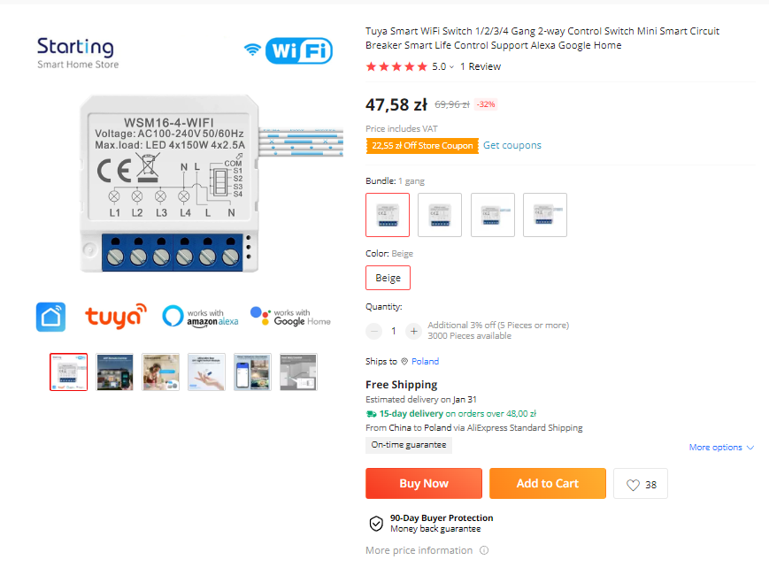
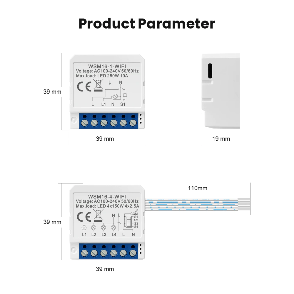
Hello, this is my first teardown of a generic Tuya-compatible smart switch with 4 ports. The model is WSM16-4.
I bought it from AliExpress:
https://a.aliexpress.com/_mM5GhGI
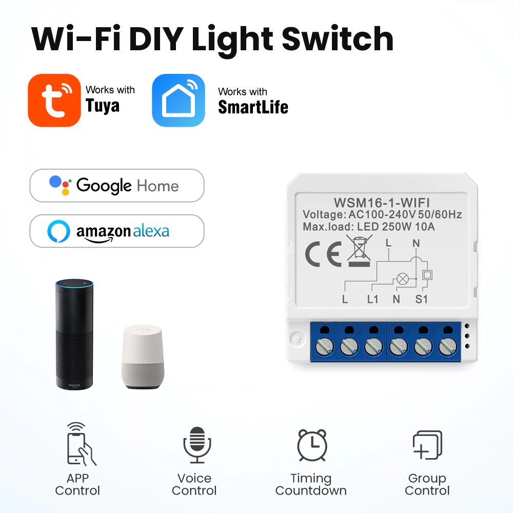
Let me also post here some screenshots from the Aliexpress link, in case it expires...


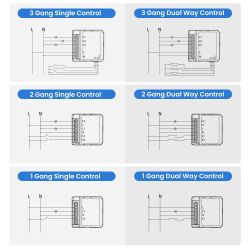
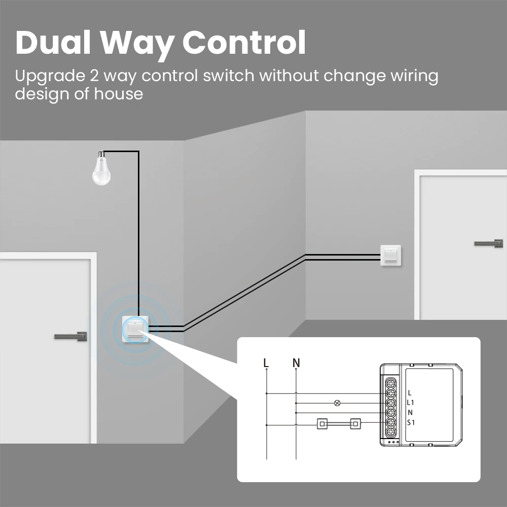
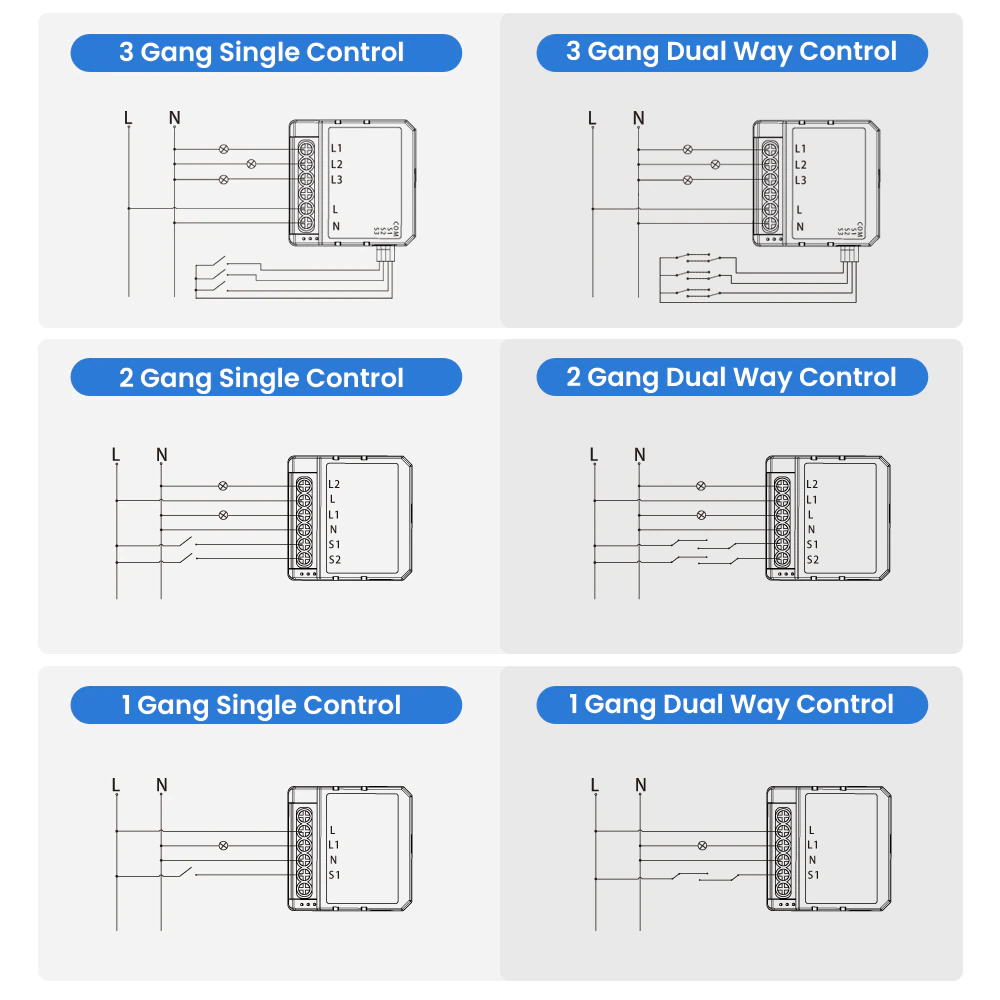
What a nice tricky way to do a dual way control.


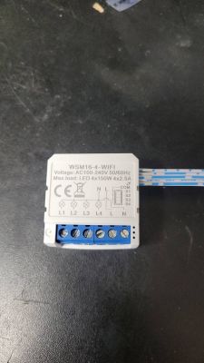

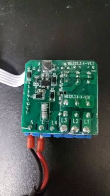
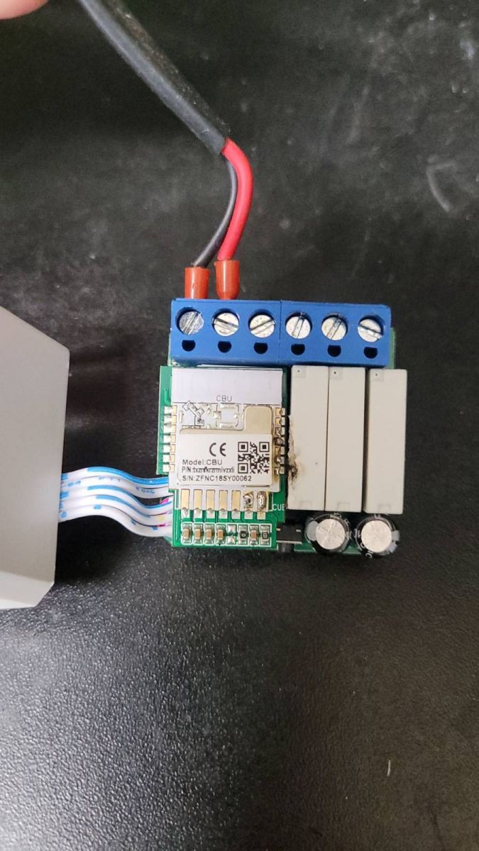
We can see that the MCU used is a CBU. These pictures were taken after disassembly and OpenBK converting, that's why there are burn marks on the plastic casing and uneven solder.
Datasheet:
https://developer.tuya.com/en/docs/iot/cbu-module-datasheet?id=Ka07pykl5dk4u
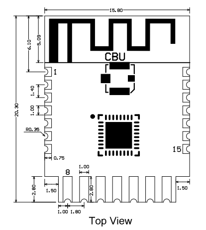
By looking at the datasheet, this is the pinout used for flashing OpenBK:


- GND: pin 13
- VCC: pin 14
- TX1: pin 15
- RX1: pin 16
- CEN: pin 18
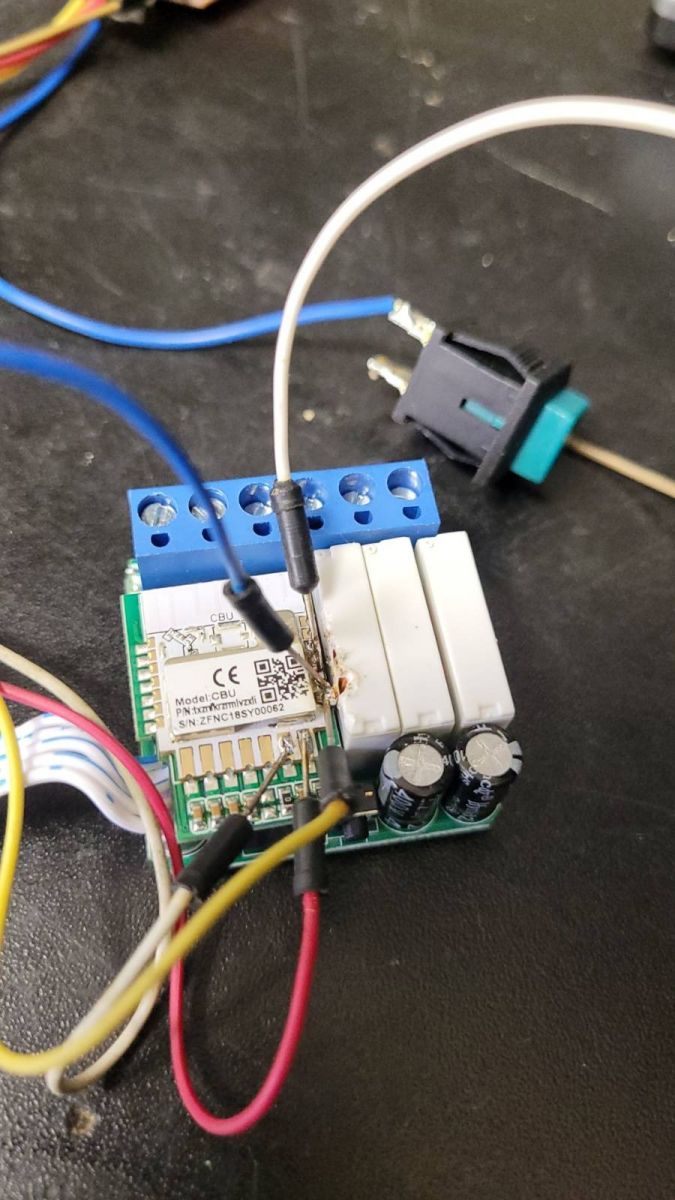
To flash OpenBK, I used a USB UART programmer and connected the cables accordingly. As usual, CEN neeeds to be grounded before flashing, so I connected CEN to a push button that grounds the pin when I press it, so the MCU can enter the bootloader mode.

I used the hid_download tool to flash, obtained from
https://github.com/OpenBekenIOT/hid_download_py and used the following parameters:
python uartprogram OpenBK7231N_QIO_1.15.206.bin --unprotect -d /dev/ttyUSB0 -w --startaddr 0x0
As soon as the program started, I pressed the push button connected to CEN to put the device into bootloader mode in order to flash the new firmware. The unprotect parameter is required, otherwise it will fail with a CRC error.
NOTE: As pointed out, the method above can be replaced by using the new Windows, user-friendly flashing tool from https://github.com/openshwprojects/BK7231GUIFlashTool
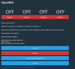
After flashing, it was time to configure the module by assigning its pins to their functions. I tried to look for existing teardowns and their setups, but unfortunately none of them had the same pinout as this "generic" module, so it was a trial and error method by connecting a light bulb to the relay outputs and testing each pin to find the correct pinout.

- P6: Btn, channel 2
- P7: Btn, channel 3
- P8: Btn, channel 4
- P9: WifiLED
- P10: Relay, channel 2
- P16: Relay, channel 4
- P17: Relay, channel 3
- P20: Relay, channel 1
- P24: Btn; this is the button originally used to pair the device, I'm using it to toggle all relays on or off.
- P26: Btn, channel 1


Comments
Thank you for presentation. I will just note here that this approach is obsolete for Windows: We have a better tool for that: https://github.com/openshwprojects/BK7231GUIFlashTool It's Windows-only,... [Read more]
Right, I was checking the GitHub right now and the readme was updated. For Linux users the hid_download method remains, right? Are you related to the development team of the project; if so, is there a... [Read more]
Thank you, the Windows GUI flasher was added very recently, one or two days ago and it's not yet popular, and wasn't test much yet as well. Don't worry much about the shop screenshots, but since you... [Read more]
I tried with .NET Core, it doesn't work because it requires .NET Framework and as far as I know the framework isn't supported on Linux. But I installed mono and ran xbuild on the project root and to my... [Read more]
Wow, that's great! I didn't even know it was possible, I am not a Linux person, I must admit. @xinayder would you be interested in contributing here, maybe adding a section "How to compile on linux"... [Read more]
Hi, i recommend using this workstation to avoid melting the plastic next to the chip with soldering iron. Or press the dupont cable to the tx/rx pin with some blue tacs. [Read more]
This is a very nice suggestion, @ferbulous , but it seems to require a special kind of filament. I didn't even know that there is such a kind of material. It wouldn't work with PLA, would it? [Read more]
@pkaczmarek2 I don't think it requires any special filament, I just had it printed online using PLA And I use this remixed version with magnet base, easier for the legs to stick on the base https://obrazki.elektroda.pl/9753974600_1673164653_thumb.jpg... [Read more]
I will try to print it with PLA and we'll see how it goes. It could make a useful article for the frontpage. I also saw TYWE3S flashing jigs somewhere. [Read more]
That one is useful for wb3s/cb3s form factor Don't see anyone making a jig for the cbu chip yet [Read more]
Good morning. I have one question. What is the purpose of changing the firmware on tuya switches? [Read more]
This allows them to be freely configurable, combined with other systems (Home Assistant), extended (add new functionality) and frees them from potential surveillance by the manufacturer (not everyone wants... [Read more]
I understand that since this works via a tuya server in China then after sflashing and changing the address that the device and the app on the phone communicate with, a soft on that server is required... [Read more]
Once flashed, this works 100% locally on your LAN. Locally you can have the Tasmota Control (OpenBeken compatible) apps on your phone and this will work, but only on your LAN. If you want worldwide... [Read more]