
One of the readers from Canada sent me a set of two 'smart' stair switches by Treatlife, model SS02 (FCC ID 2ANIFSS01), for analysis/programming. "3-Way-Smart-Switch", offering e.g. control of their status via WiFi. I will see here how such switches are implemented, how they look in the application and I will try to change their firmware to
OpenBeken .
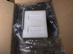
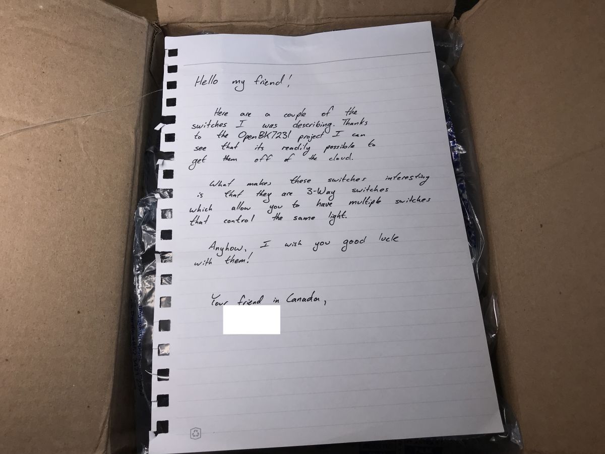
package from Canada
Some time ago I received this set, along with a dedication -
thank you very much! If you want to send anything else, please contact me via PM :


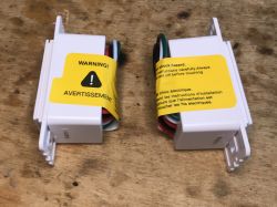
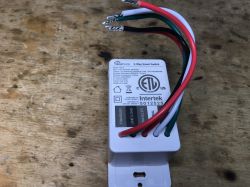
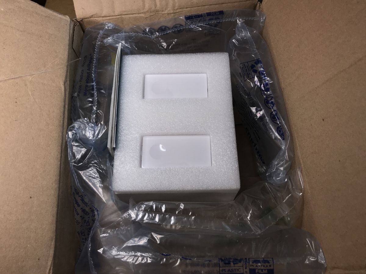
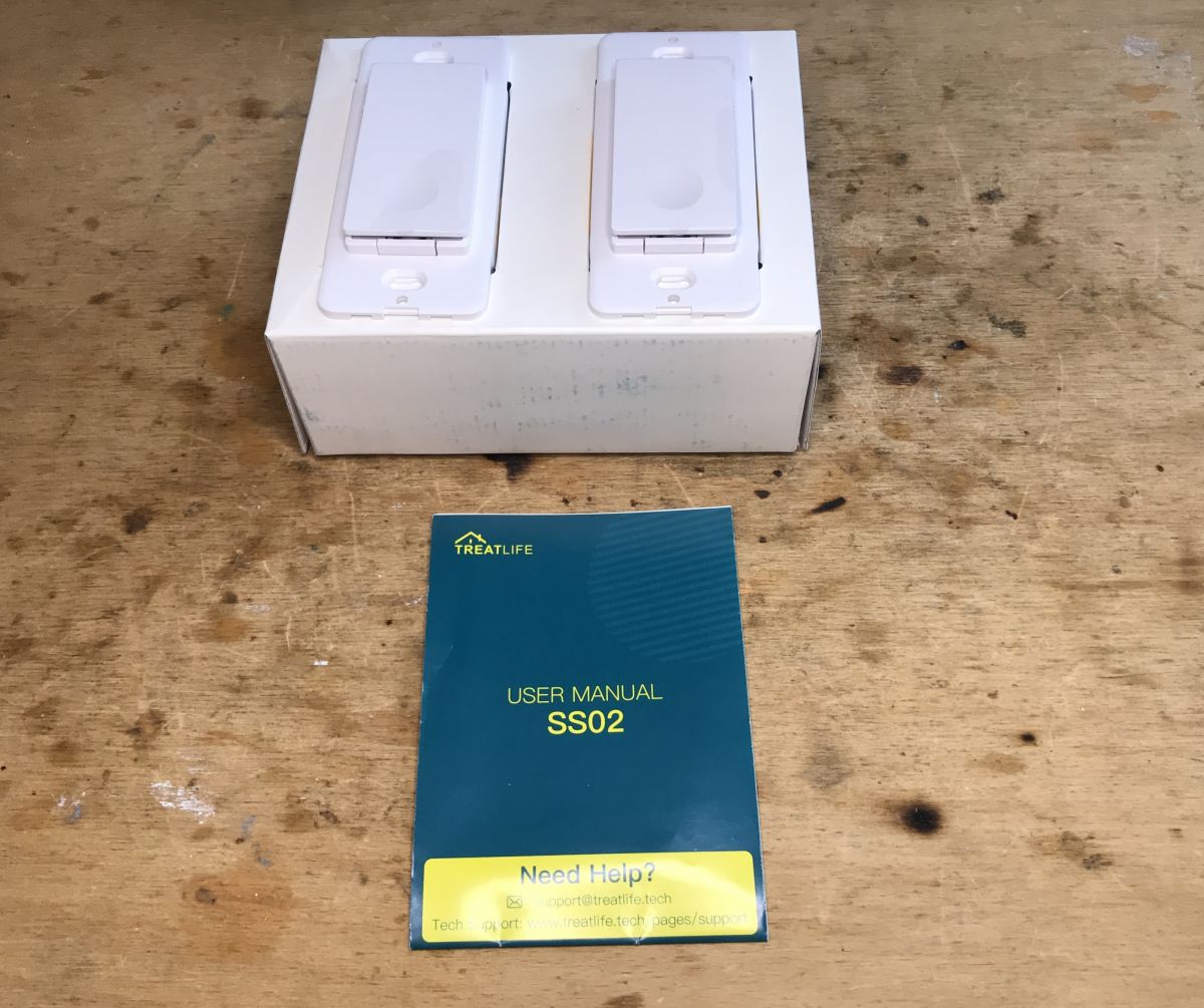
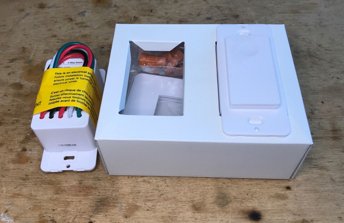
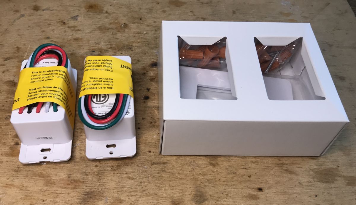
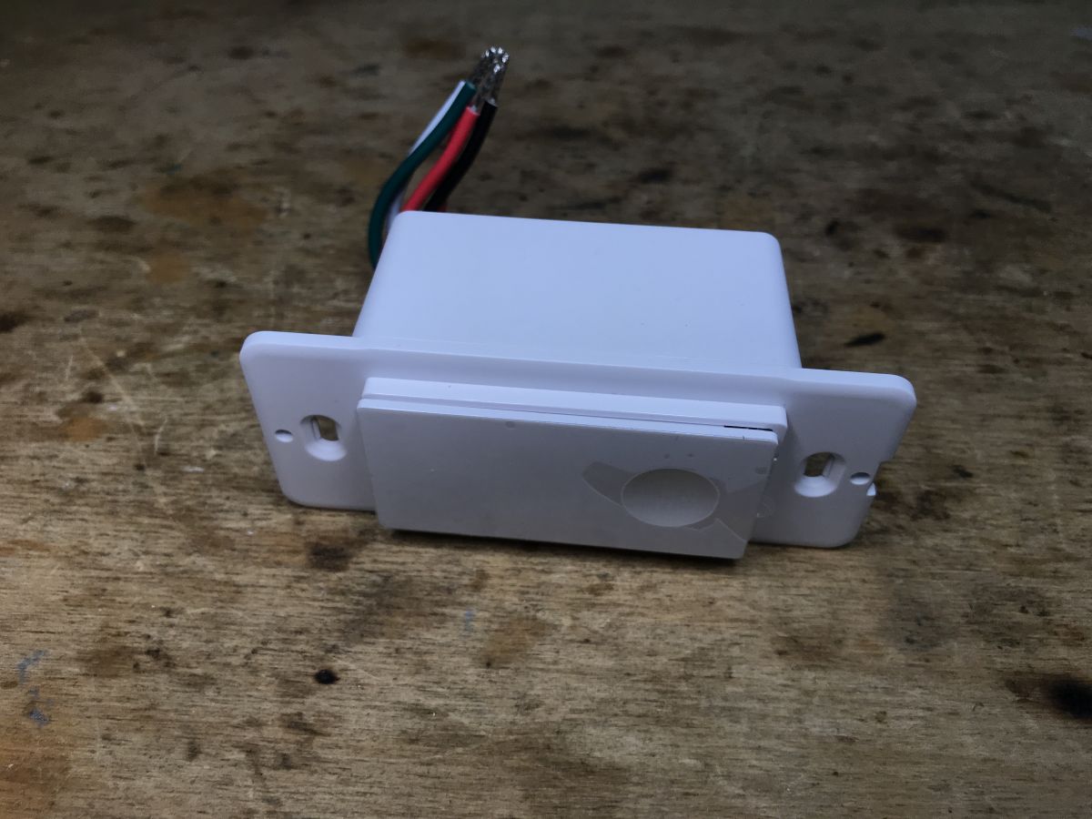
What do we have here... a set of two switches - TreatLife SS02, stair switches, but in the "smart" version.

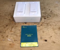
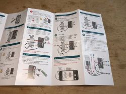
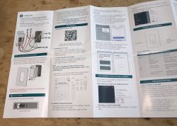
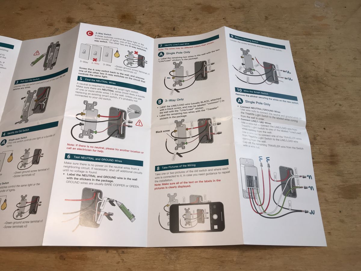
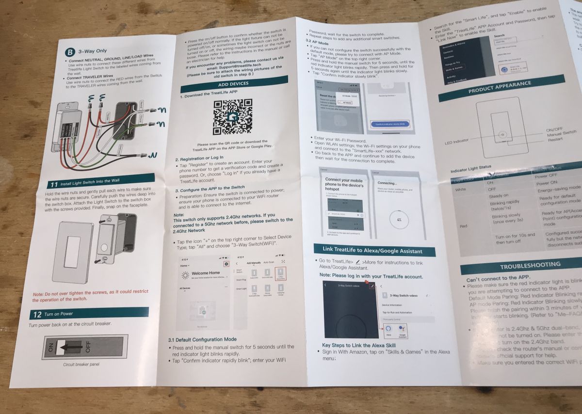
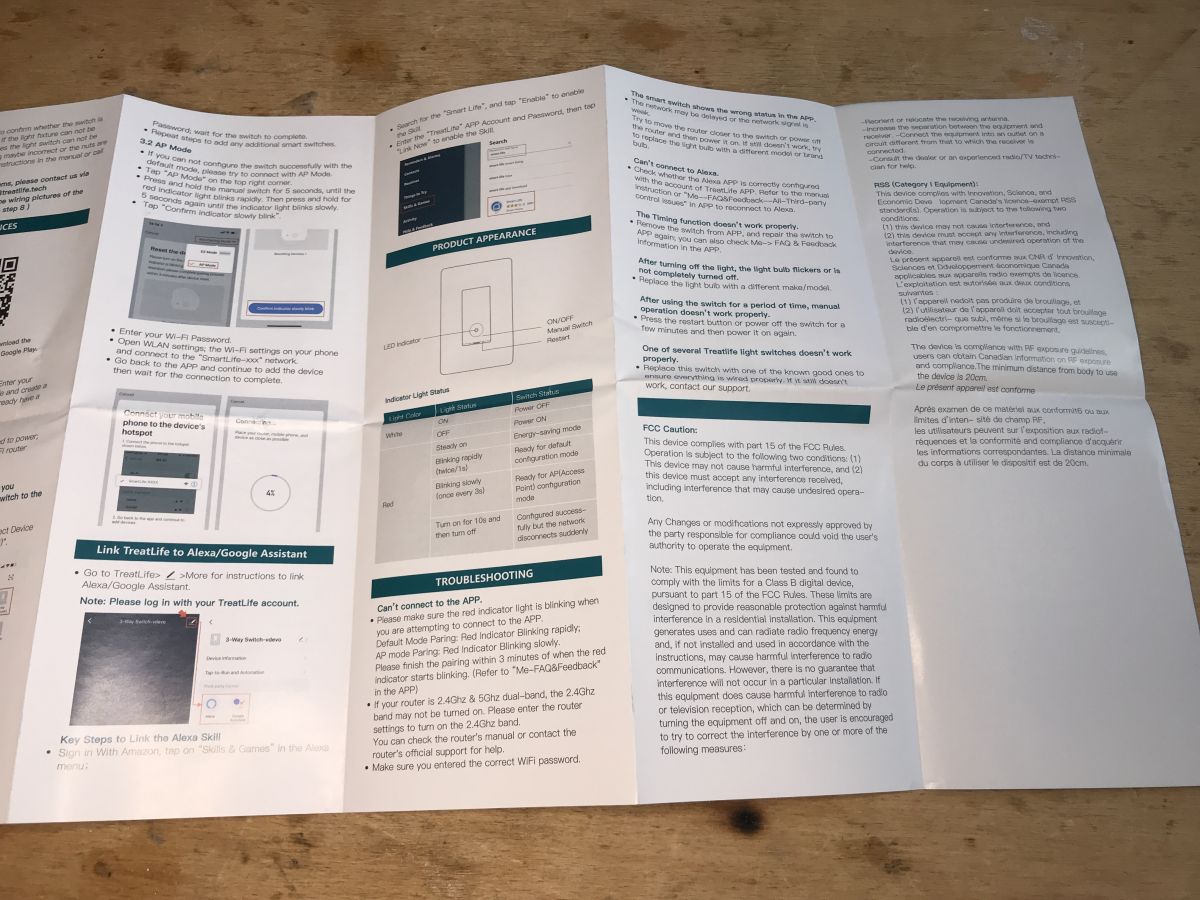
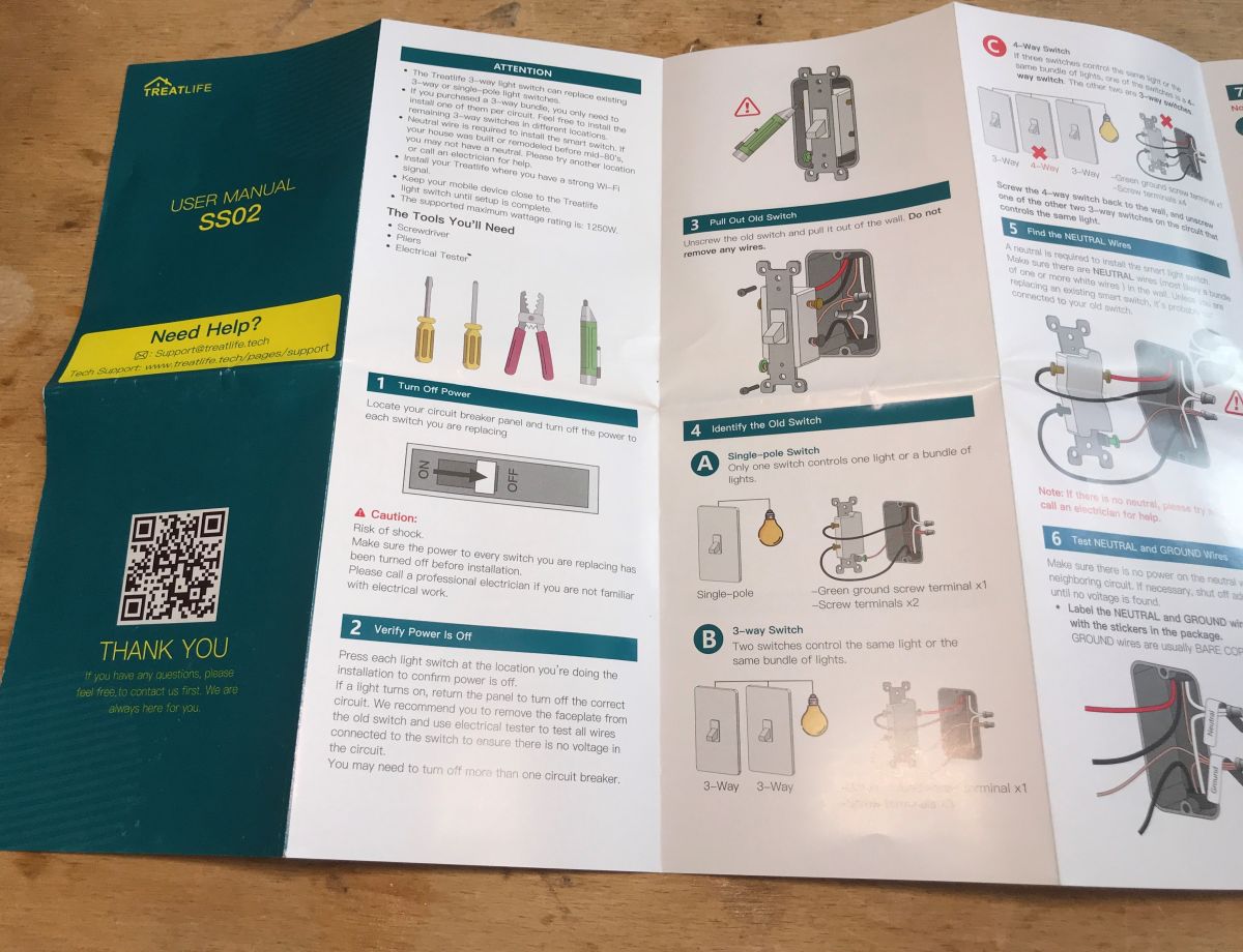
Instructions (I recommend getting to know both operating modes - the normal switch mode and the staircase mode):


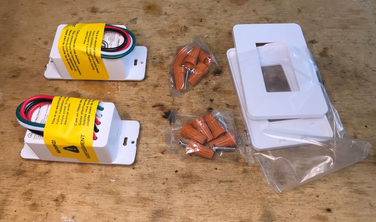
The switches also contain screws for mounting and caps for connecting wires:


 But let's start with how an ordinary stair switch works.
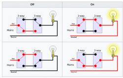
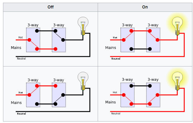
As the name suggests, it occurs e.g. just by the stairs - let's imagine that we have one lamp (above the stairs) and two switches - one at the top of the stairs, the other at the bottom. How can it be connected so that both switches switch the state of the lamp?
This image from Wikipedia illustrates it well:
(
graphics licensed under the CC BY-SA 3.0 license )
We have two two-state buttons and additionally they are released
two wires , so-called "traveler" (that's how they are signed in this set), but the current flows at most only one of them at a time. The switches are mounted in such a way that a change in the state of one of them always either turns on or off the circuit.
But how is it implemented in the 'smart' version?
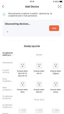
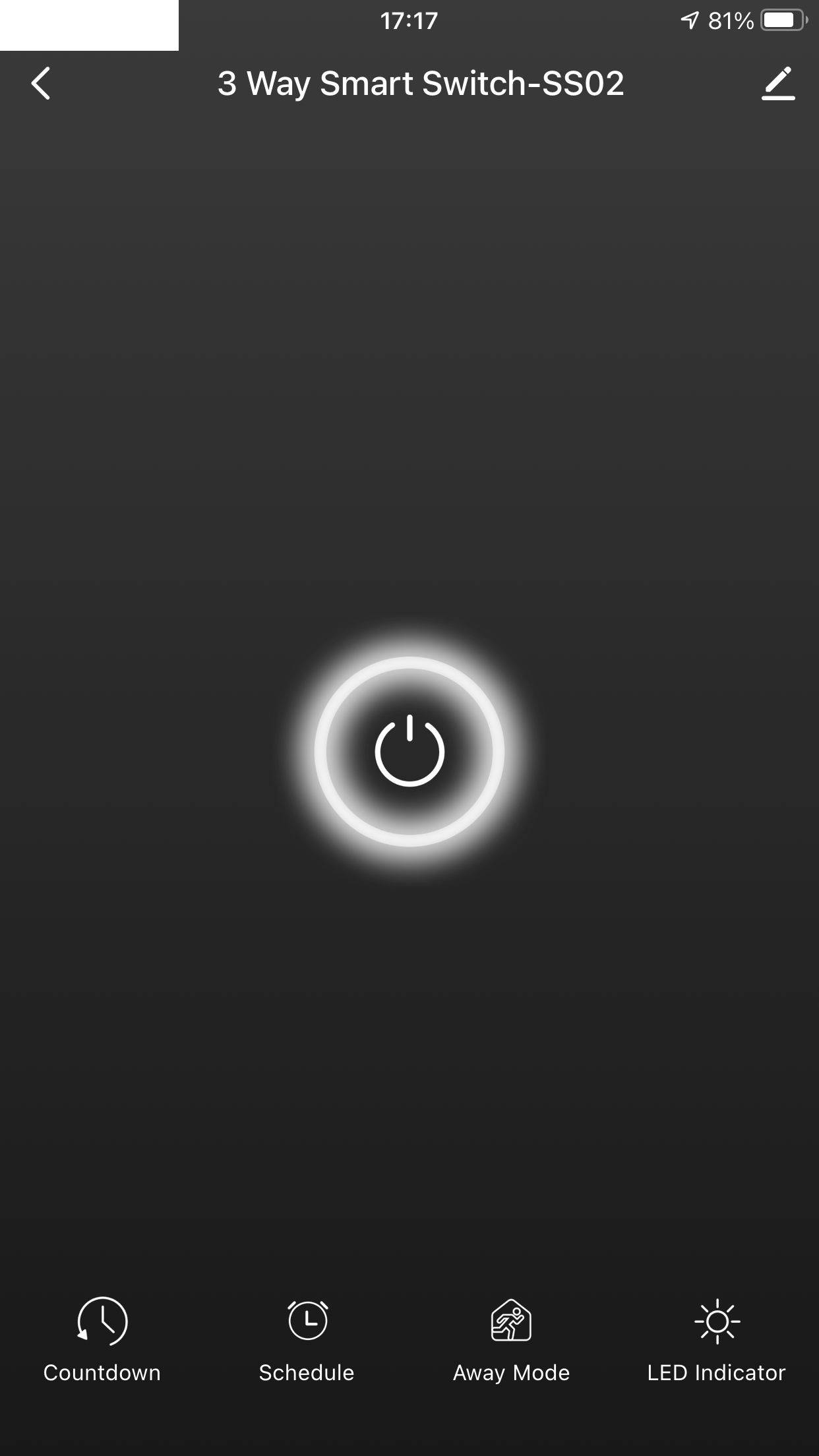
In-app view
Applications like Blitzwolf, Tuya, SmartLife have already been discussed on the forum. This time very briefly.
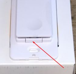
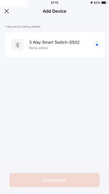
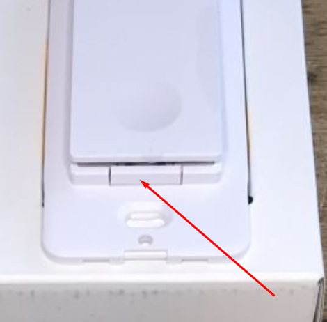
This little button is used to enter pairing mode:
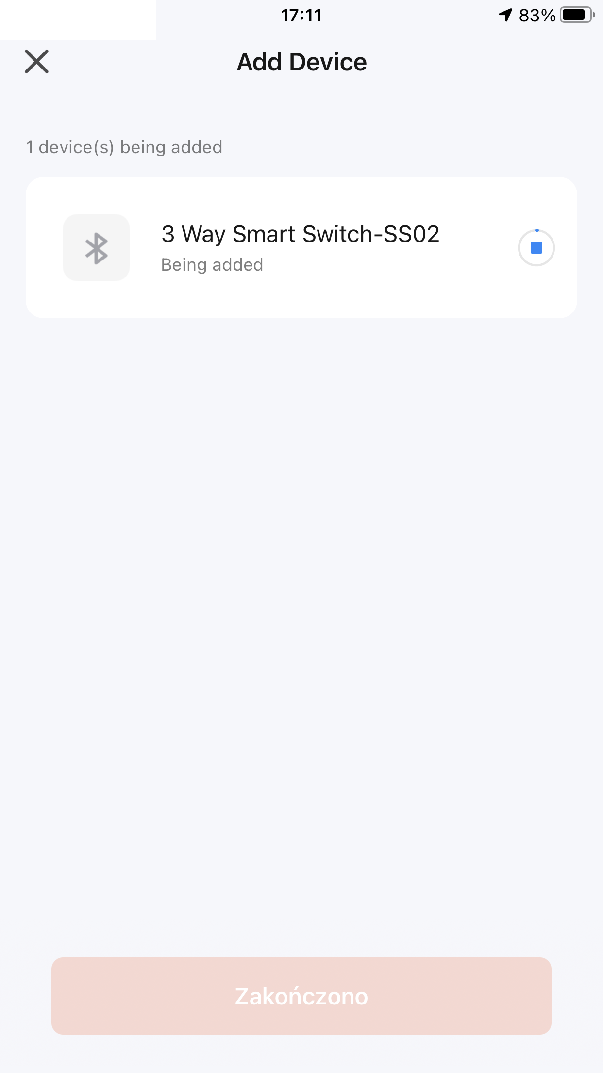
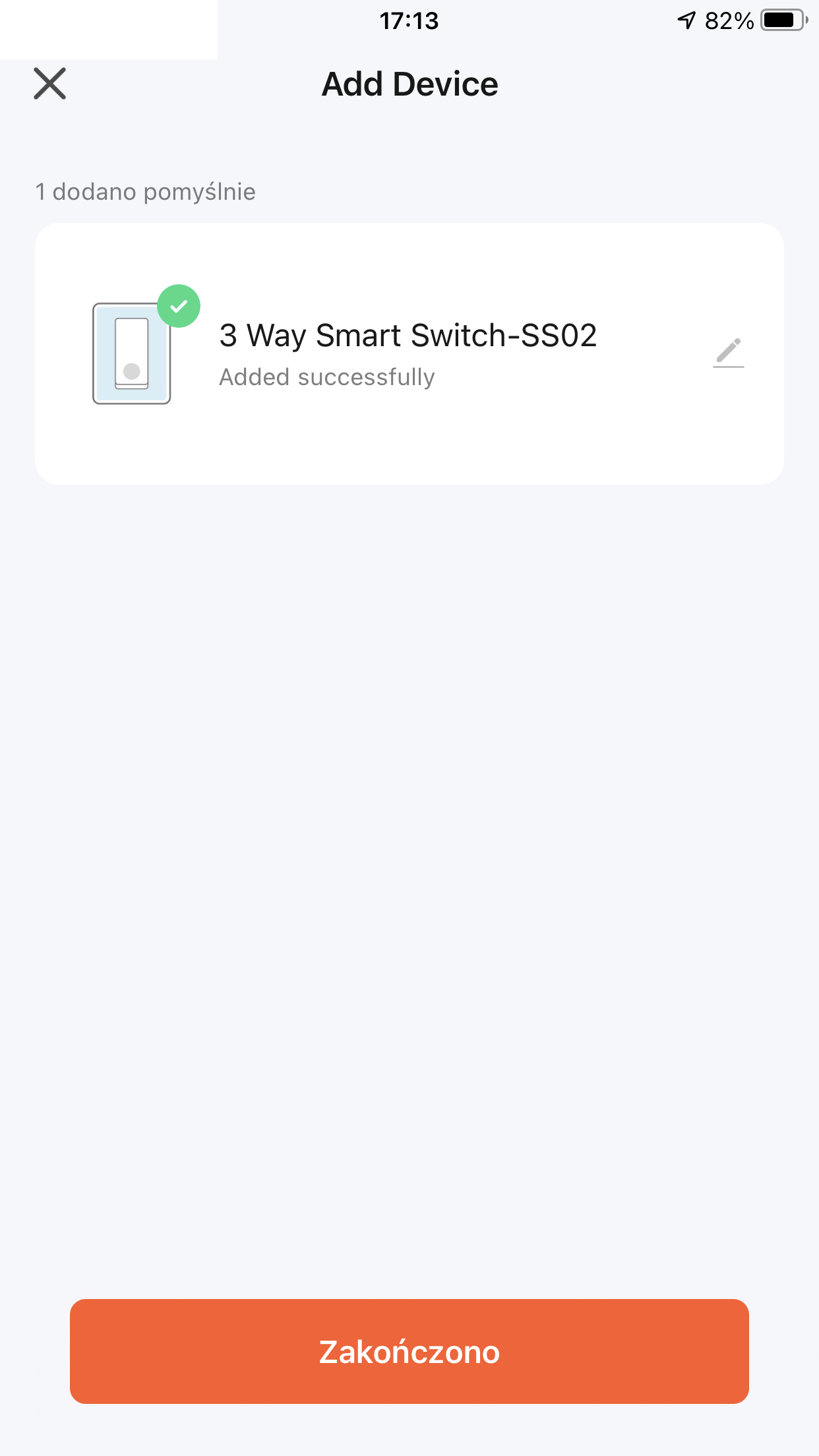
I paired with the Tuya app, there were no problems.
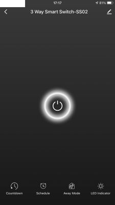
 In the application, it is striking that Tuya does not know whether the light is on or not
 - and yet it could be checked on the basis of the initial states of the switches (with the appropriate connection of the wires marked as "traveler")
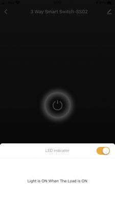
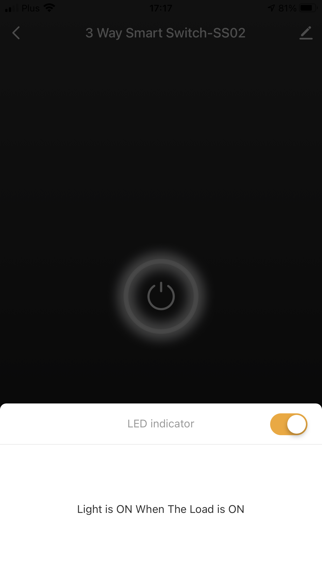
In the switch configuration, I also see some remnants of the functionality of an ordinary switch, e.g. the ability to combine the state of the LED with the state of the relay (or negate them), only
what sense does it make if the second stairway has an unknown state to us?
It would make sense if the application somehow paired two selected stair switches and would know if the light is on - but for me it didn't even show the light status ...
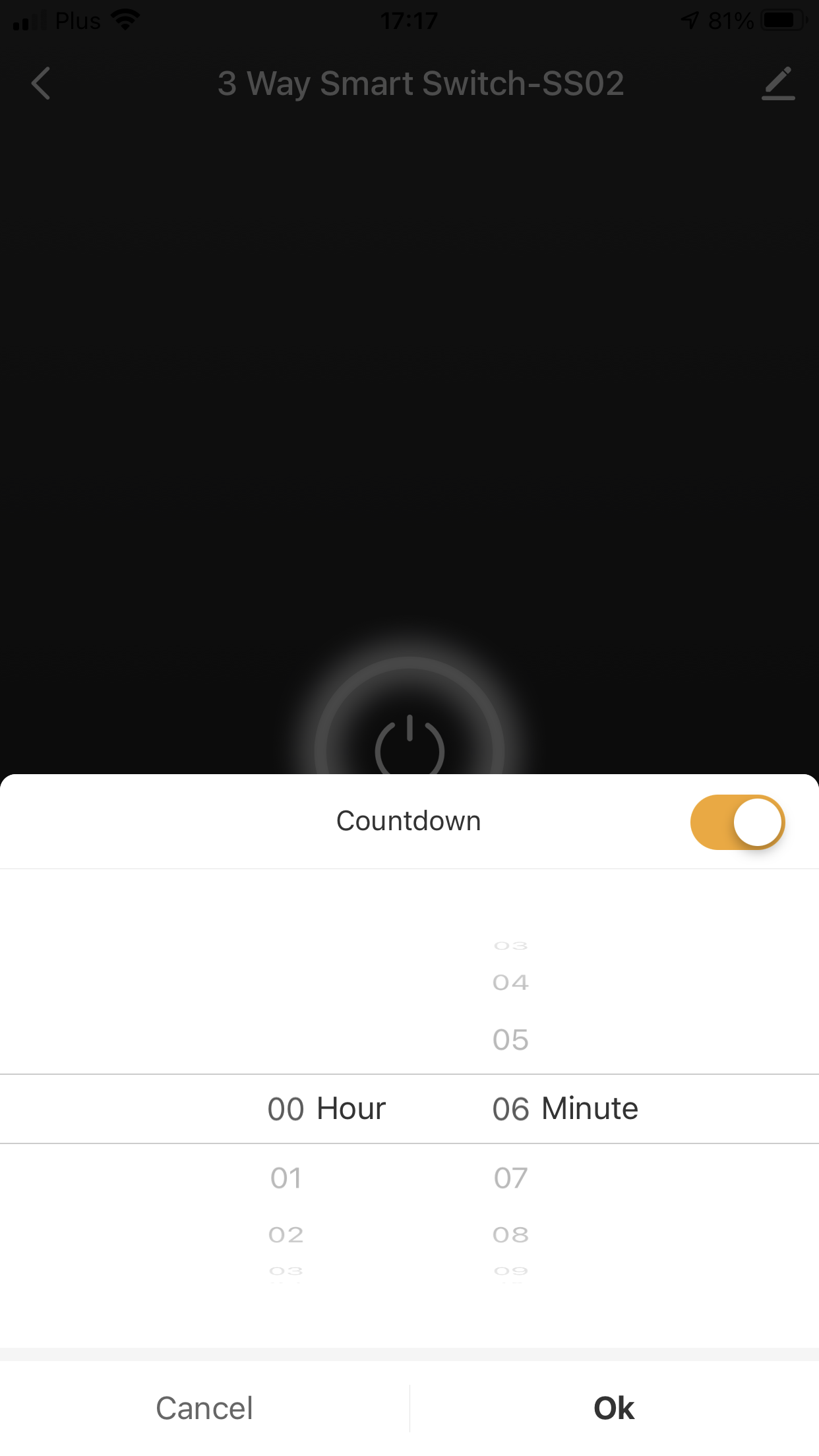
Of course, you can also set a countdown, which after a given time simply changes the state of the relay to the opposite.
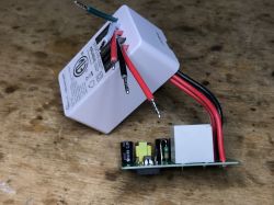
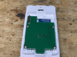
 We look inside
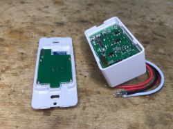
It is enough to pry the housing, but you need to use some force. The hooks are very strong.
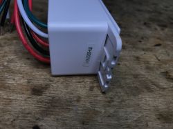
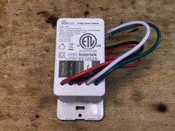
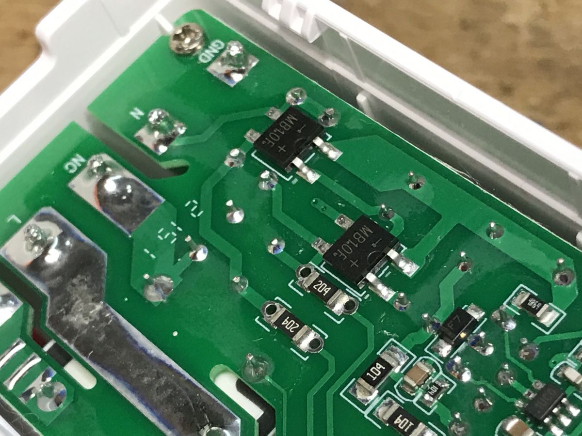
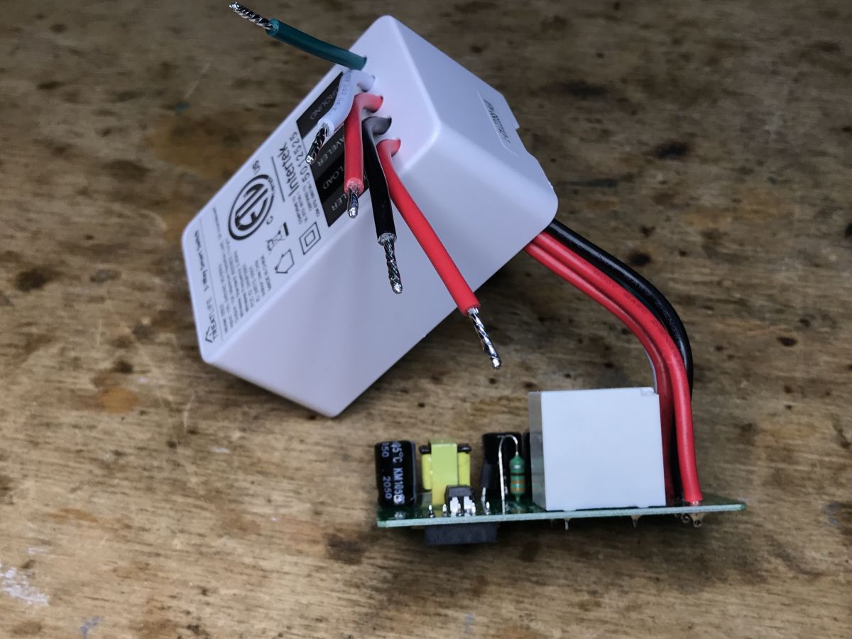
The switch has pins: Traveler (same marking twice), Line/Load, Neutral and Ground.
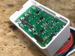
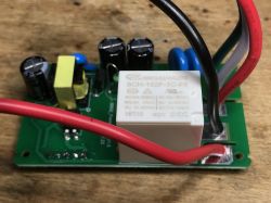
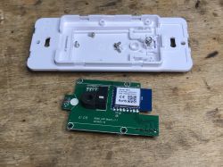
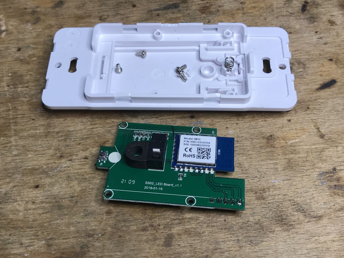
There are two PCBs inside, one with the WiFi module and the other with the power supply, relay, etc:
What do we have here...

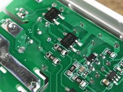

 So it's a relay. A single relay simulating a switch, both NO (normally open) and NC (normally closed) contacts are used.
 It is to them that the 'traveler' signals are connected.
It is known - if we switch the state in one switch, the circuit either disconnects or turns on, and then if we switch the state in the other switch, we can turn it on or off accordingly.
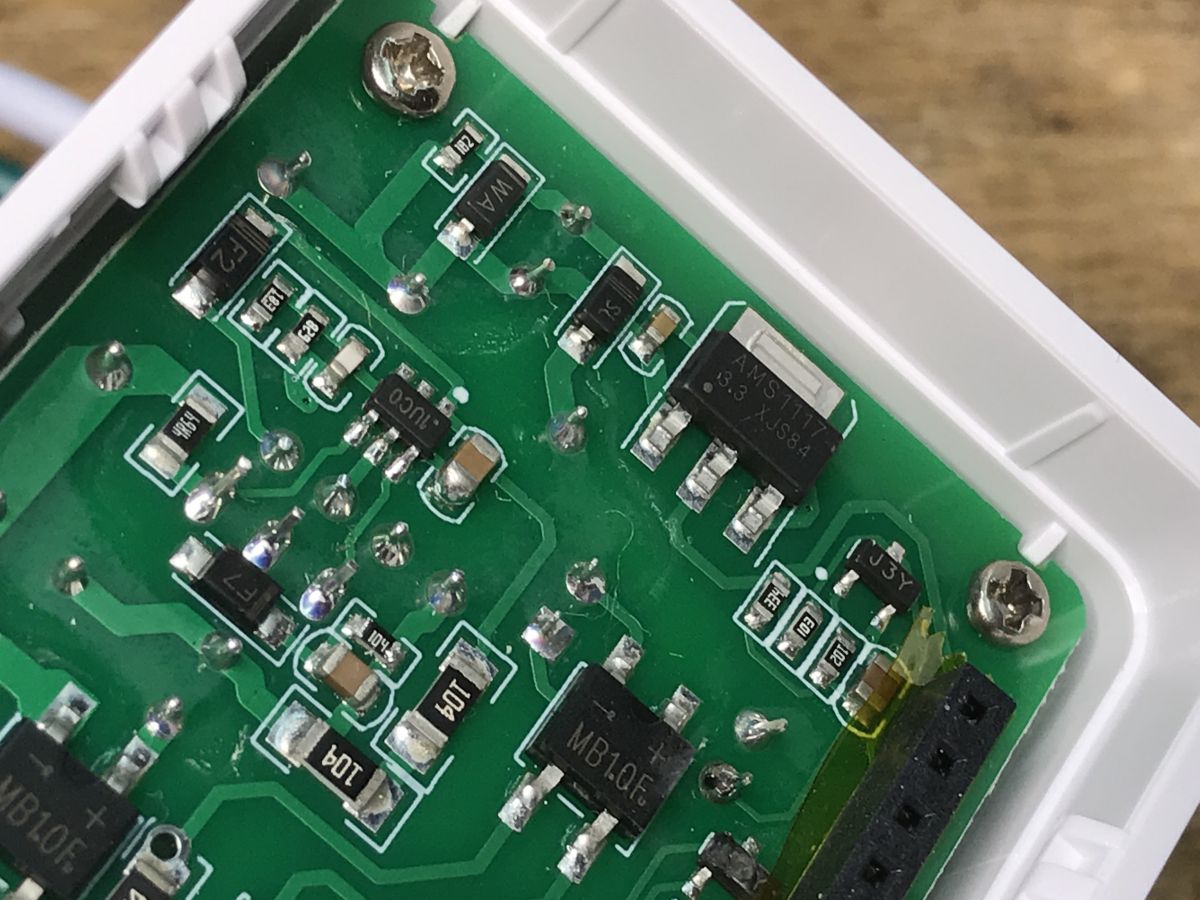
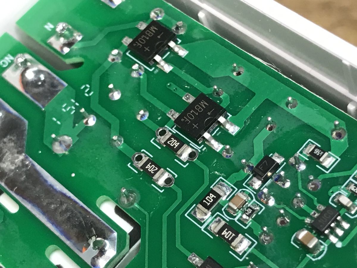
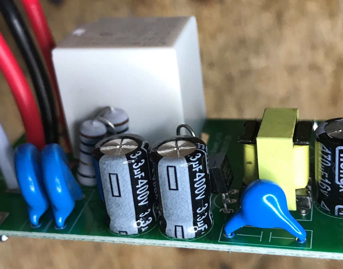
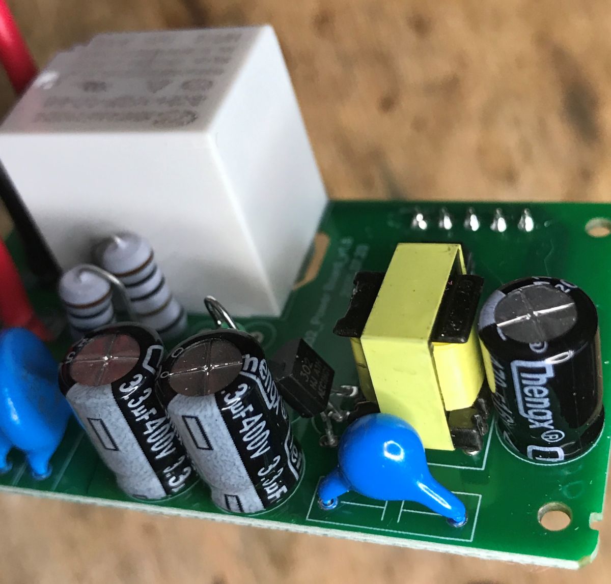
In addition, the rectifier bridges MB10F catch the eye. There are as many as three.
A short analysis explains why they were connected in this way - so that they can also power the system from the NO and NC lines.
In addition, there is a simple power supply here, giving about 5V for the relay and AMS1117-3.3 powering the BK7231.
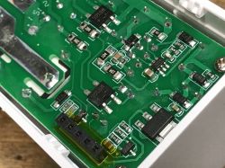
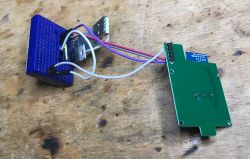
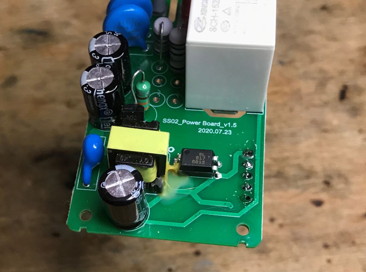
What's on the other side of the PCB?
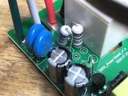
The relay is the SCH-152F-1C-5S model for 5V.
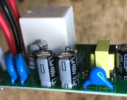


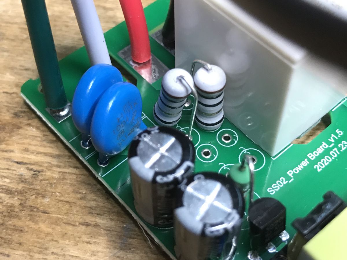
You can see the transformer from the power supply, the optocoupler EL817, the class Y capacitor next to the power supply connecting the primary and secondary sides, in the background you can see fuse resistors and
varistors surge protection. Is not so bad. Not every manufacturer uses even these varistors.
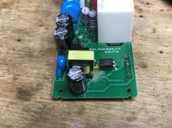
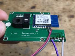
Now the WiFi board:
You need to unscrew some screws. Be careful not to lose the spring!
Inside is the WB3S module, i.e. BK7231T. Classic. Fully supported.
 Load change
We program as in the previous topic in the series:
Light switch from USA - Gosund Smart Switch SW5-A-V2.1 - BK7231T
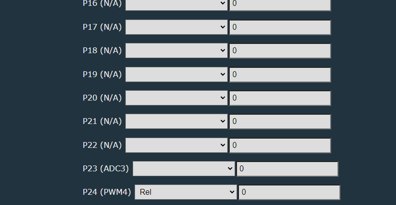
Here is my programming layout:
 After changing the software, of course, in the case of the stairway configuration, the same problem will continue - but I don't worry about it, because the same can be done using Tasmota Device Groups and then we get really "smart" stair switches
 :
Tasmota Device Groups - connection of OpenBeken (BK7231T/BK7231N) with Tasmota
Of course, this solution also has its big disadvantage - if our WiFi network fails, the 'smart' stair switches lose their pairing. In addition, it must be remembered that this requires connecting the light to only one switch, in the usual way, and the second switch then only via DGR transmits messages about changes. You can also use free buttons, e.g. a three-button switch - as I did here:
Recessed switch controlling other devices from home - Tasmota Device Groups
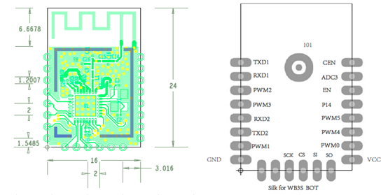
It remains to specify the roles of the pins:

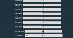
One more thing to add here -
RESET button, this onea tiny button under the main button, it is connected to CEN - it performs a normal RESET of the WiFi module, it is not on its GPIO controllable by OBK .
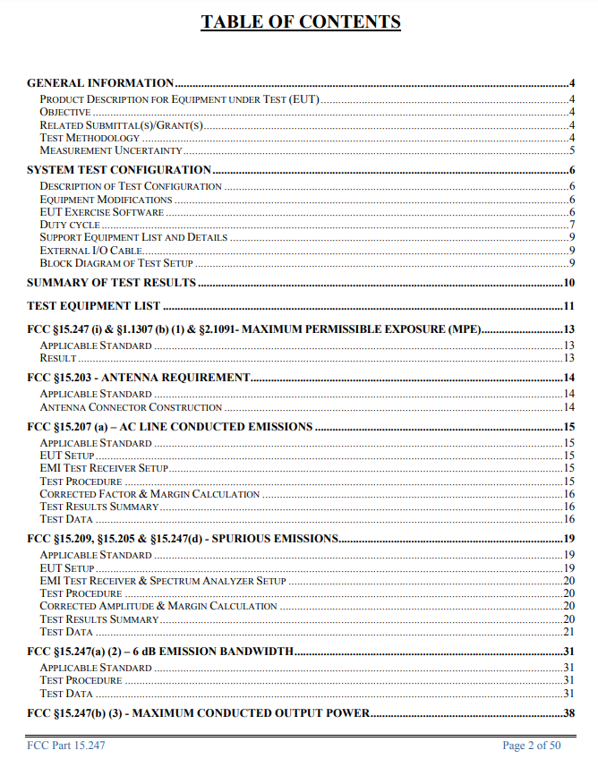
Interesting fact - FCC report
Under the keyword "2ANIFSS01" you can find a fairly detailed analysis of this product online, or rather its earlier version, still on TYWE3S, from 2019:

You can find the manual here:
2ANIFSS01_...Manual.pdf (787.67 kB)You must be logged in to download this attachment.
Outside photos:
2ANIFSS01_...Photos.pdf (359.77 kB)You must be logged in to download this attachment.
From inside (TYWE3S version):
2ANIFSS01_...Photos.pdf (686.86 kB)You must be logged in to download this attachment.
And even a detailed analysis of RF emissions and interference:
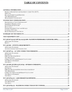 2ANIFSS01_...Report.pdf (895.03 kB)You must be logged in to download this attachment.
Summary
2ANIFSS01_...Report.pdf (895.03 kB)You must be logged in to download this attachment.
Summary
The device turned out to be very interesting and I was happy to analyze it, thank you again for sending it to me, but I must admit that the manufacturer's idea itself was not as 'smart' as it could be.
The main downside of this set is that, to my surprise, the mobile application simply "doesn't know" whether the light is on or not.
Maybe it's because I paired it with Tuya app and not with Treatlife, but still, I didn't work as expected.
This greatly limits, to quote marketers, the "intelligence" of this solution.
This makes it impossible to create automations such as "turn off the light at 23:30" because the application does not know whether the change in the state of the relay will turn the light on or off.
Similarly, it prevents the execution of a simple scenario called "turn off all the lights in the house" because, as above, the application does not know if the light is on.
This could be fixed in a simple way - if during the assembly we made sure that both switches with an open relay did not result in a lit light, then the application could simply check the status of both and check whether only one of them has a shorted relay - if so, then the light is lit, otherwise it is not.
But the app doesn't - it doesn't even show if the light is on or off.
It can also be fixed in the style proposed in the topic (Tasmota Device Groups - that is, there would simply be one switch, the second relay would be permanently open and the second one would only send status change messages to the first one via WiFi, via DGR ), this would also enable more advanced automations to be performed on them.
The advantage of this product is the presence of fuses and varistors, as well as the presence of a filter made of two electrolytic capacitors and a choke at the input of the power supply. A large part of the cheapest products from China do not even have such basic things, and here they are present.


Comments
I don't understand the underlying implementation but the previous version using ESP8266 could tell whether the load was energized or not with Tasmota firmware. If Treatlife merely replaced the SOC and... [Read more]
Yes, we were not aware about it at the time of writing this teardown, but we've managed to realize it soon later. https://www.elektroda.com/rtvforum/viewtopic.php?p=20713493#20713493 ADCSmoother driver... [Read more]
Is there more to it than something analogous to using the appropriate YAML template in the ESPHome Addon in HA? Going further upstream than that might be too much for me :-( Thanks [Read more]