The UltraPro WFD4001 is a 120V 3-way Wifi smart switch under the UltraPro brand of Jasco. It uses a WB3S Tuya chip, which can be exploited over the air using Tuya-Cloudcutter.
Purchase link: Amazon
Manufacturer Instructions: UltraPro WFD 4001
Alternate Wiring: Alternate Wiring
Product Image:
![[BK7231T WB3S] UltraPro WFD4001 3-Way Smart Wall Switch [BK7231T WB3S] UltraPro WFD4001 3-Way Smart Wall Switch](https://obrazki.elektroda.pl/2017773700_1675123553_thumb.jpg)
Teardown:
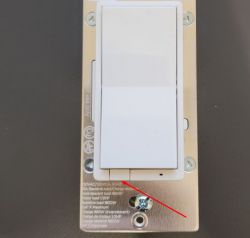
This is pretty easy to get into, just pop off the front switch cover by pulling on the tabs on either side. Once the front cover is off, you can easily get to the 4 triangle screws (not sure the proper name of these, but I happened to have a bit in a precision screwdriver set from Klein). Once these are removed, the entire metal faceplate can be easily removed.
![[BK7231T WB3S] UltraPro WFD4001 3-Way Smart Wall Switch [BK7231T WB3S] UltraPro WFD4001 3-Way Smart Wall Switch](https://obrazki.elektroda.pl/4175131500_1675123929_thumb.jpg)
![[BK7231T WB3S] UltraPro WFD4001 3-Way Smart Wall Switch [BK7231T WB3S] UltraPro WFD4001 3-Way Smart Wall Switch](https://obrazki.elektroda.pl/1092390000_1675123935_thumb.jpg)
![[BK7231T WB3S] UltraPro WFD4001 3-Way Smart Wall Switch [BK7231T WB3S] UltraPro WFD4001 3-Way Smart Wall Switch](https://obrazki.elektroda.pl/7458179300_1675123937_thumb.jpg)
![[BK7231T WB3S] UltraPro WFD4001 3-Way Smart Wall Switch [BK7231T WB3S] UltraPro WFD4001 3-Way Smart Wall Switch](https://obrazki.elektroda.pl/7773412000_1675123939_thumb.jpg)
![[BK7231T WB3S] UltraPro WFD4001 3-Way Smart Wall Switch [BK7231T WB3S] UltraPro WFD4001 3-Way Smart Wall Switch](https://obrazki.elektroda.pl/2917220400_1675123942_thumb.jpg)
![[BK7231T WB3S] UltraPro WFD4001 3-Way Smart Wall Switch [BK7231T WB3S] UltraPro WFD4001 3-Way Smart Wall Switch](https://obrazki.elektroda.pl/9395919100_1675123949_thumb.jpg)
The board is split into two parts that I will call the control board and the power board. Both of these boards can be removed by just pulling them out, no other screws or tabs are holding them in, although the power board is held in a little bit by the screws terminals, but these can be pushed out from the side. The control board sits on top and has the WB3S chip, as well as the up and down buttons. This is connected to the power board via a 6-pin header, so be careful to pull the control board straight out so the pins don't get bent. A closer look at the 6-pins has them labeled as REL, 5V, GND, 3-WAY, ZEROX, and NC. The REL is also labeled as PWM in some spots - I'm not sure if this is because it terminates to a PWM pin on the WB3S chip, or if there is some other functionality that I don't know about. I could not find where the NC and ZEROX pins go to, so I'm not sure what they are used for. The NC doesn't seem to go anywhere on the board, but the ZEROX looks to be connected to a few components.
![[BK7231T WB3S] UltraPro WFD4001 3-Way Smart Wall Switch [BK7231T WB3S] UltraPro WFD4001 3-Way Smart Wall Switch](https://obrazki.elektroda.pl/2790634000_1675124344_thumb.jpg)
![[BK7231T WB3S] UltraPro WFD4001 3-Way Smart Wall Switch [BK7231T WB3S] UltraPro WFD4001 3-Way Smart Wall Switch](https://obrazki.elektroda.pl/6784794700_1675124347_thumb.jpg)
![[BK7231T WB3S] UltraPro WFD4001 3-Way Smart Wall Switch [BK7231T WB3S] UltraPro WFD4001 3-Way Smart Wall Switch](https://obrazki.elektroda.pl/3955295100_1675124350_thumb.jpg)
![[BK7231T WB3S] UltraPro WFD4001 3-Way Smart Wall Switch [BK7231T WB3S] UltraPro WFD4001 3-Way Smart Wall Switch](https://obrazki.elektroda.pl/3242979800_1675124354_thumb.jpg)
![[BK7231T WB3S] UltraPro WFD4001 3-Way Smart Wall Switch [BK7231T WB3S] UltraPro WFD4001 3-Way Smart Wall Switch](https://obrazki.elektroda.pl/2056015200_1675124361_thumb.jpg)
![[BK7231T WB3S] UltraPro WFD4001 3-Way Smart Wall Switch [BK7231T WB3S] UltraPro WFD4001 3-Way Smart Wall Switch](https://obrazki.elektroda.pl/5790746600_1675124367_thumb.jpg)
The power board has an 0B2222MCP chip which is described as a "PWM Power Switch", but I'm not sure if there is anything useful for us here.
![[BK7231T WB3S] UltraPro WFD4001 3-Way Smart Wall Switch [BK7231T WB3S] UltraPro WFD4001 3-Way Smart Wall Switch](https://obrazki.elektroda.pl/2975645700_1675126514_thumb.jpg)
As mentioned earlier, this device can be exploited with tuya-cloudcutter. There is already a device-profile available for it making the conversion pretty easy.
Because this switch has 2 buttons, the config has a bit more steps than normal, but not too bad.
Settings:
You will need to create some event handlers to properly handle the buttons. I did this by creating an autoexec.bat file with the following code:
3-Way:
I still haven't figured this out yet, but here is the progress that I've made. Using a multimeter, I determined that the 3-WAY pin connects directly to the ADC3 pin on the WB3S module (0Ω). It looks like the 3-WAY pin also goes to a KL4 chip which looks to be an ADC chip as well, but I couldn't find where it goes from here. When I set the ADC3 pin to ADC mode and put it on its own channel, I can get some values, but nothing that is exactly usable to control the 3-way function. When the traveler wire is low, the ADC values hover in the range of 15-27. When the traveler is high (120V), the ADC output seems to slowly go from the same low range, all the way to 4095 which I assume is the max that can be measured, but then falls back to the low values. It just cycles from low to high indefinitely. I tried watching all of the other pins to see if anything happens when I switch the traveler, but so far I haven't found anything. I don't think I wired anything incorrectly, as I tried the same configuration with a stock switch and it worked fine with the traveler.
Not sure if anyone has experience with something similar, but any help figuring this out would be much appreciated!
Purchase link: Amazon
Manufacturer Instructions: UltraPro WFD 4001
Alternate Wiring: Alternate Wiring
Product Image:
![[BK7231T WB3S] UltraPro WFD4001 3-Way Smart Wall Switch [BK7231T WB3S] UltraPro WFD4001 3-Way Smart Wall Switch](https://obrazki.elektroda.pl/2017773700_1675123553_thumb.jpg)
Teardown:
This is pretty easy to get into, just pop off the front switch cover by pulling on the tabs on either side. Once the front cover is off, you can easily get to the 4 triangle screws (not sure the proper name of these, but I happened to have a bit in a precision screwdriver set from Klein). Once these are removed, the entire metal faceplate can be easily removed.
![[BK7231T WB3S] UltraPro WFD4001 3-Way Smart Wall Switch [BK7231T WB3S] UltraPro WFD4001 3-Way Smart Wall Switch](https://obrazki.elektroda.pl/4175131500_1675123929_thumb.jpg)
![[BK7231T WB3S] UltraPro WFD4001 3-Way Smart Wall Switch [BK7231T WB3S] UltraPro WFD4001 3-Way Smart Wall Switch](https://obrazki.elektroda.pl/1092390000_1675123935_thumb.jpg)
![[BK7231T WB3S] UltraPro WFD4001 3-Way Smart Wall Switch [BK7231T WB3S] UltraPro WFD4001 3-Way Smart Wall Switch](https://obrazki.elektroda.pl/7458179300_1675123937_thumb.jpg)
![[BK7231T WB3S] UltraPro WFD4001 3-Way Smart Wall Switch [BK7231T WB3S] UltraPro WFD4001 3-Way Smart Wall Switch](https://obrazki.elektroda.pl/7773412000_1675123939_thumb.jpg)
![[BK7231T WB3S] UltraPro WFD4001 3-Way Smart Wall Switch [BK7231T WB3S] UltraPro WFD4001 3-Way Smart Wall Switch](https://obrazki.elektroda.pl/2917220400_1675123942_thumb.jpg)
![[BK7231T WB3S] UltraPro WFD4001 3-Way Smart Wall Switch [BK7231T WB3S] UltraPro WFD4001 3-Way Smart Wall Switch](https://obrazki.elektroda.pl/9395919100_1675123949_thumb.jpg)
The board is split into two parts that I will call the control board and the power board. Both of these boards can be removed by just pulling them out, no other screws or tabs are holding them in, although the power board is held in a little bit by the screws terminals, but these can be pushed out from the side. The control board sits on top and has the WB3S chip, as well as the up and down buttons. This is connected to the power board via a 6-pin header, so be careful to pull the control board straight out so the pins don't get bent. A closer look at the 6-pins has them labeled as REL, 5V, GND, 3-WAY, ZEROX, and NC. The REL is also labeled as PWM in some spots - I'm not sure if this is because it terminates to a PWM pin on the WB3S chip, or if there is some other functionality that I don't know about. I could not find where the NC and ZEROX pins go to, so I'm not sure what they are used for. The NC doesn't seem to go anywhere on the board, but the ZEROX looks to be connected to a few components.
![[BK7231T WB3S] UltraPro WFD4001 3-Way Smart Wall Switch [BK7231T WB3S] UltraPro WFD4001 3-Way Smart Wall Switch](https://obrazki.elektroda.pl/2790634000_1675124344_thumb.jpg)
![[BK7231T WB3S] UltraPro WFD4001 3-Way Smart Wall Switch [BK7231T WB3S] UltraPro WFD4001 3-Way Smart Wall Switch](https://obrazki.elektroda.pl/6784794700_1675124347_thumb.jpg)
![[BK7231T WB3S] UltraPro WFD4001 3-Way Smart Wall Switch [BK7231T WB3S] UltraPro WFD4001 3-Way Smart Wall Switch](https://obrazki.elektroda.pl/3955295100_1675124350_thumb.jpg)
![[BK7231T WB3S] UltraPro WFD4001 3-Way Smart Wall Switch [BK7231T WB3S] UltraPro WFD4001 3-Way Smart Wall Switch](https://obrazki.elektroda.pl/3242979800_1675124354_thumb.jpg)
![[BK7231T WB3S] UltraPro WFD4001 3-Way Smart Wall Switch [BK7231T WB3S] UltraPro WFD4001 3-Way Smart Wall Switch](https://obrazki.elektroda.pl/2056015200_1675124361_thumb.jpg)
![[BK7231T WB3S] UltraPro WFD4001 3-Way Smart Wall Switch [BK7231T WB3S] UltraPro WFD4001 3-Way Smart Wall Switch](https://obrazki.elektroda.pl/5790746600_1675124367_thumb.jpg)
The power board has an 0B2222MCP chip which is described as a "PWM Power Switch", but I'm not sure if there is anything useful for us here.
![[BK7231T WB3S] UltraPro WFD4001 3-Way Smart Wall Switch [BK7231T WB3S] UltraPro WFD4001 3-Way Smart Wall Switch](https://obrazki.elektroda.pl/2975645700_1675126514_thumb.jpg)
As mentioned earlier, this device can be exploited with tuya-cloudcutter. There is already a device-profile available for it making the conversion pretty easy.
Because this switch has 2 buttons, the config has a bit more steps than normal, but not too bad.
Settings:
| Pin # | Pin Name | Description | Settings |
| P8 | PWM2 | Up Button | Btn_ScriptOnly |
| P9 | PWM3 | Down Button | Btn_ScriptOnly |
| P24 | PWM4 | Front LED | LED or LED_n |
| P26 | PWM5 | Switch Relay | Rel |
You will need to create some event handlers to properly handle the buttons. I did this by creating an autoexec.bat file with the following code:
addEventHandler OnClick 8 setChannel 1 1
addEventHandler OnClick 9 setChannel 1 0
3-Way:
I still haven't figured this out yet, but here is the progress that I've made. Using a multimeter, I determined that the 3-WAY pin connects directly to the ADC3 pin on the WB3S module (0Ω). It looks like the 3-WAY pin also goes to a KL4 chip which looks to be an ADC chip as well, but I couldn't find where it goes from here. When I set the ADC3 pin to ADC mode and put it on its own channel, I can get some values, but nothing that is exactly usable to control the 3-way function. When the traveler wire is low, the ADC values hover in the range of 15-27. When the traveler is high (120V), the ADC output seems to slowly go from the same low range, all the way to 4095 which I assume is the max that can be measured, but then falls back to the low values. It just cycles from low to high indefinitely. I tried watching all of the other pins to see if anything happens when I switch the traveler, but so far I haven't found anything. I don't think I wired anything incorrectly, as I tried the same configuration with a stock switch and it worked fine with the traveler.
Not sure if anyone has experience with something similar, but any help figuring this out would be much appreciated!
Cool? Ranking DIY


![[BK7231T WB3S] UltraPro WFD4001 3-Way Smart Wall Switch [BK7231T WB3S] UltraPro WFD4001 3-Way Smart Wall Switch](https://obrazki.elektroda.pl/2630953900_1675212355_thumb.jpg)
![[BK7231T WB3S] UltraPro WFD4001 3-Way Smart Wall Switch [BK7231T WB3S] UltraPro WFD4001 3-Way Smart Wall Switch](https://obrazki.elektroda.pl/6279067100_1675212356_thumb.jpg)


