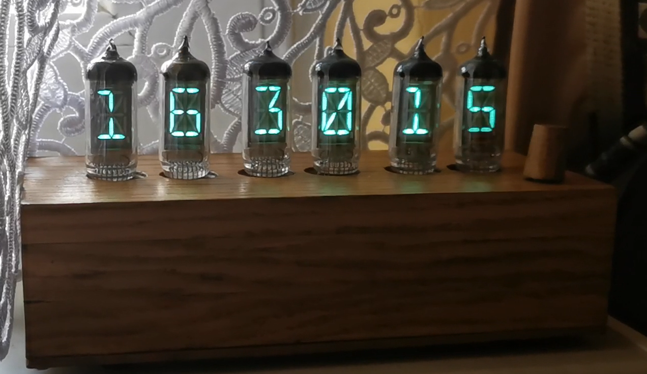
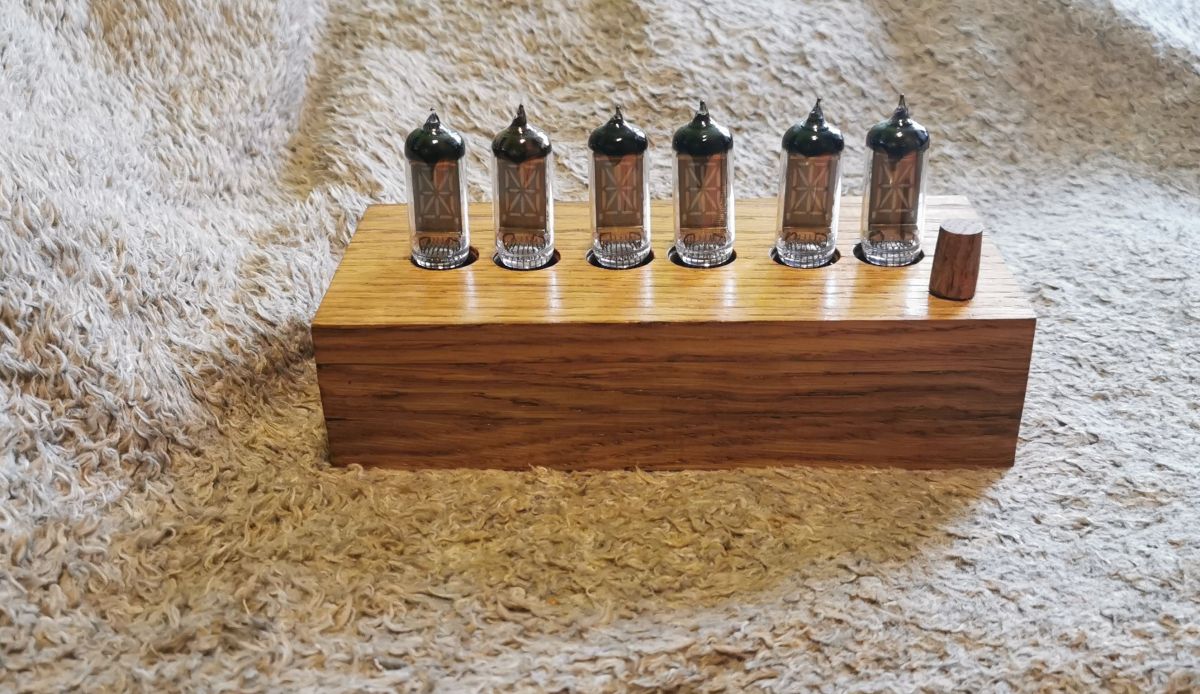
Description and presentation below , designed and made by me, clock based on VFD IV-17 tubes . The impulse to make the clock is largely inspired by the video presentation of the Wiktor clock in action:
Having previously made a clock on the IV18 lamp (and gained some experience), I decided that it was time to start with a much more complicated - much more representative 18-segment IV17 lamp. Note here: IV4 (IV-4, ИВ-4) and IV17 (IV-17, ИВ-17) tubes are replacements, and sometimes the designation IV4 may appear in this description.
The main assumptions for the design of the IV17 clock
- clock on 6 IV17 tubes; - use of the HV integrated circuit to control the segments (in the IV18 clock I used NPN keys to control the segments, it's possible, but a lot of extra work); - the control element will be STM32F103.
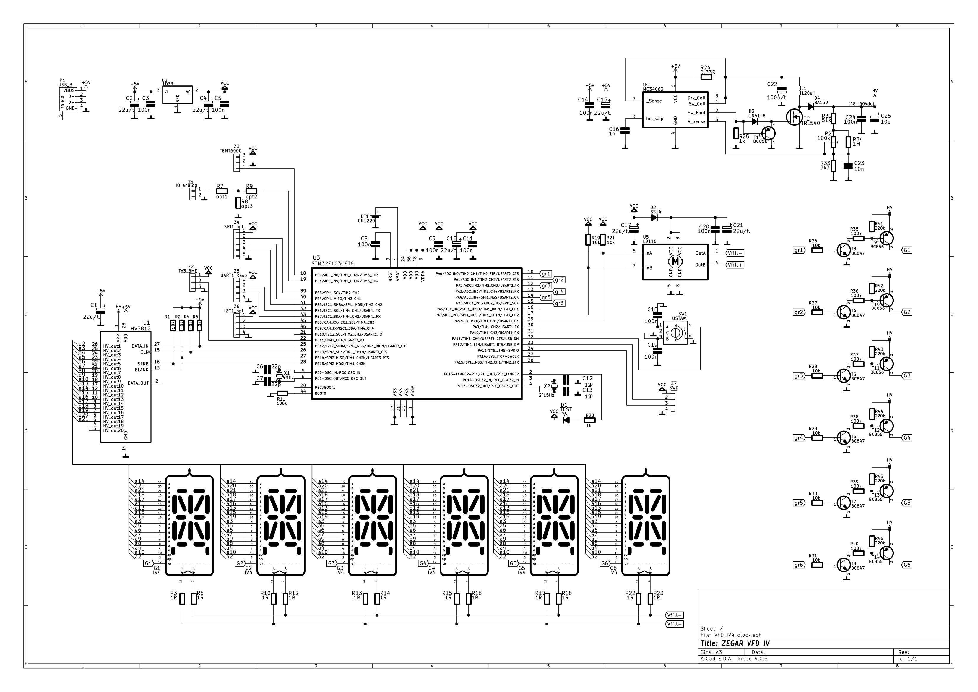
Scheme of the clock IV17
Overview of the essential circuits:
The construction of the clock boils down to the proper power supply and logic operation of 6 VFD IV17 tubes. By assumption, for the 18-segment VFD, the mode of operation with multiplexed display was selected.
A 120µH inductor (Imax > 1 A) was used, a MOSFET transistor IRL540 with reduced turn-on voltage U GS(th) . The output voltage of this DC-DC converter is 45 V. This voltage value was selected in order to extend the life of the VFD lamps (for multiplexed operation, the note suggests 50-70 Vdc, for static operation 25-30 Vdc) while maintaining sufficient brightness.
The power supply of the lamp filaments with 1R resistors included in the circuits was selected so as to ensure the catalog operating conditions U fill ~2.4 V. The polarity of the glow potential was changed - the integrated circuit of the L9110 bridge was used.
CONTROL
According to the assumptions, the SMT32F103C8T6 microcontroller was used (used e.g. in BluePill modules). The main control of the 18 segments is carried out by means of the HV5812 integrated high-voltage demultiplexer (a simple serial protocol with timing), while the 45 Vdc switching for the grids of 6 IV17 lamps was performed on the NPN (BC847)-PNP (BC856) keys. For the sake of clarity, the 18 220k resistors accelerating the discharge of the switched anode voltages are not shown.
The system has an active battery backup circuit (CR1220), the time source is an internal RTC with an external 32768 Hz quartz connected. Correction of RTC clock accuracy is possible in two stages (correction_1 of 24h time and correction_2 of 14 days) by entering deviations in settings menu . There are 5 levels of display brightness adjustment - this is done by changing the duty factor (Ugrid activity) for a given time slot of a specific VFD lamp. max. lighting level of VFD lamps selected in settings menu.
U neigh polarity change timing fill through outputs (PWM 50%) complementary Timer1 - with a frequency of approx. 102 Hz.
The clock is prepared to work with data from the weather station, which it receives via USART3_9600 (Z2 connector) as a frame with 28B (temperature, pressure, humidity, ubatt, lux, - description of the frame in the attachment *txt). Work without the above data from the weather station is possible, only the VFD lighting level - then it is not automatically set to the current value of natural lighting [lux] received from the weather station.
Settings menu available via classic encoder: up/down/enter. In the settings you can select: display mode (only_time/time+date/time+weather_data), max. VFD lighting level, enter: 2 degrees of clock accuracy corrections.
Due to the large number of available digital interfaces in the STM32F1, an interface for possible communication with Raspberry I/O, other devices via SPI or I2C has been added to the diagram.
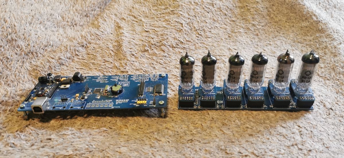
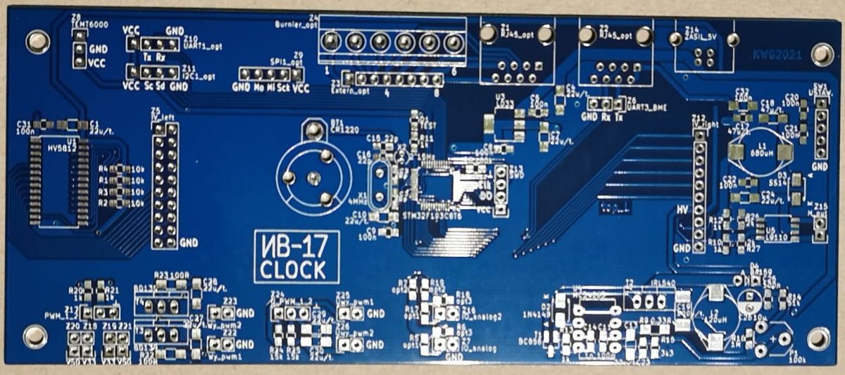
HOUSING, PCB - execution
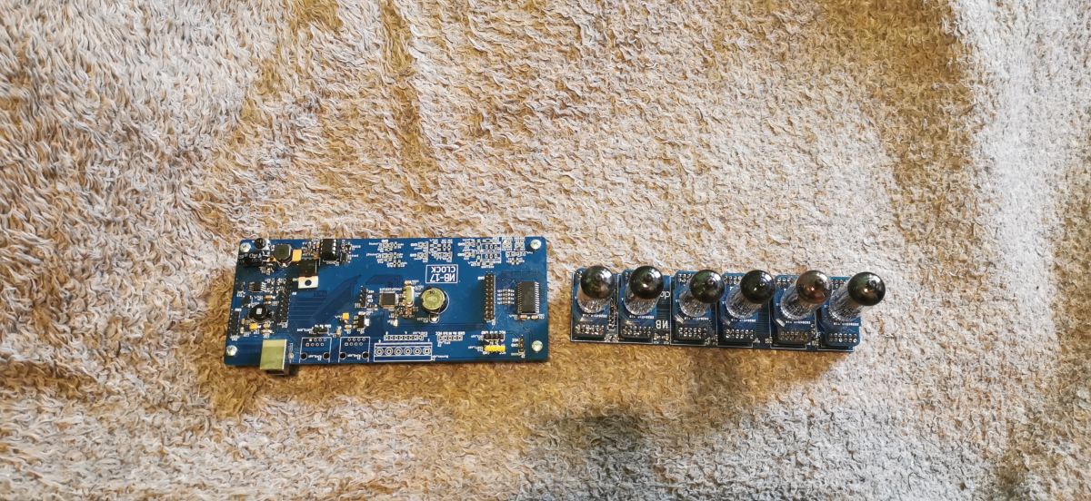
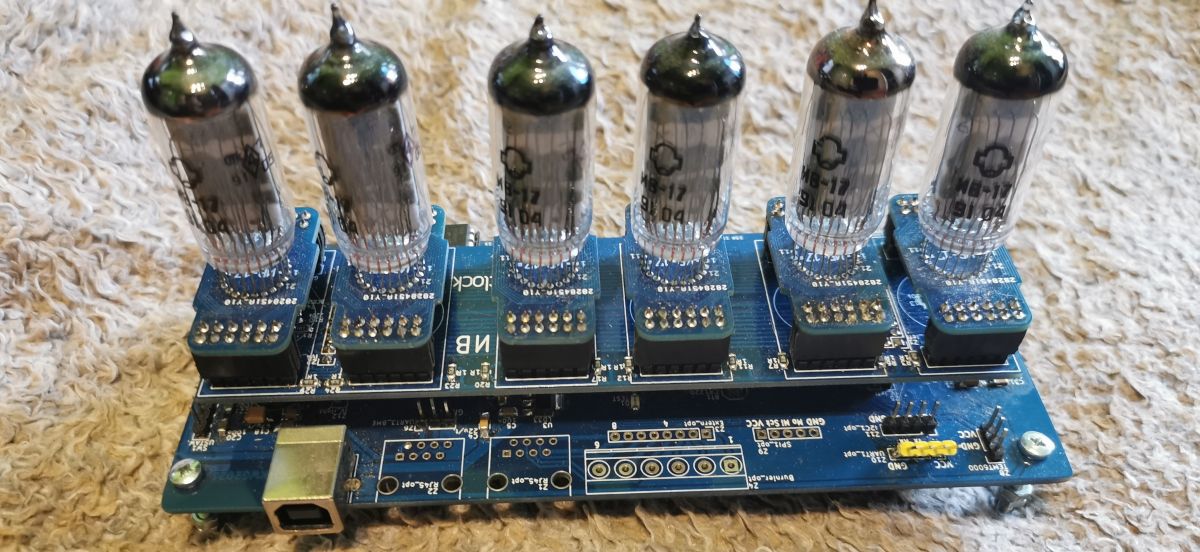
The actual execution of the clock is based on 3 PCBs: – main board includes: µC, all power supply circuits, HV5812 segment driver, USART, SPI, I2C interfaces; – Display intermediate board includes: NPN (BC847)-PNP(BC856) keys to control 6 grids of VFD tubes, 2xIDC12 connectors for each IV17 tube; – VFD IV17 tube board includes: 2xIDC12 connectors, 1 IV17 tube. Such a division of the pcb gives a certain versatility to build a clock/device based on other VFD tubes (for example IV11 for me). Then only dedicated boards for the VFD lamp and redesign of a simple intermediate display board are needed. The motherboard with µC remains unchanged.
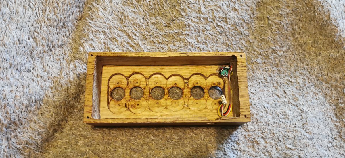
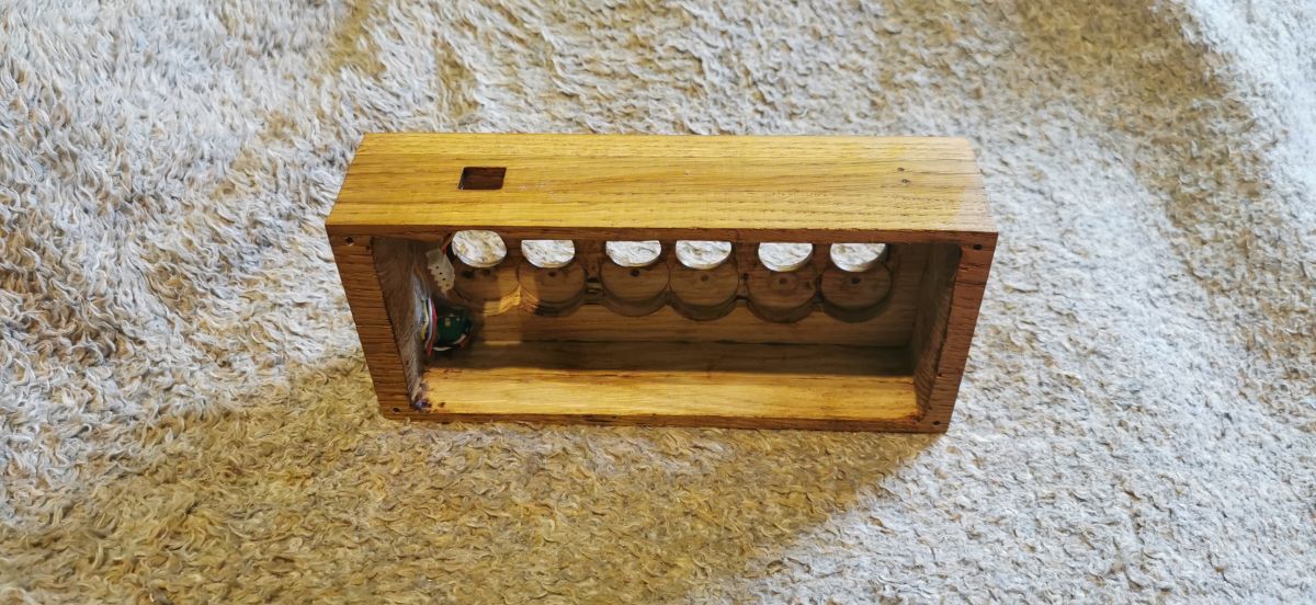
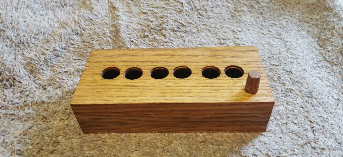
Wooden casing made of ordered cut 3 oak planks 17 mm glued together, forming the proper shape. Then, the place for the PCBs was carefully drilled and 20 mm holes were drilled for the VFD lamps, 6 mm holes for the encoder and a hole for the USB_print power connector. The lower part of the housing is covered with a cut 3 mm fibreboard. All painted with shellac.
The startup itself went smoothly, the power supply on the MC34063 generates 45 V, the voltage practically does not drop when the display is loaded. The clock supply current of about 400 mA is mainly the current of the lamp heating circuits (I fill approx. 300mA).
A separate matter is the µC software, defining your own characters for the 18-segment display and developing ways to correct the inaccuracy of the 32768 Hz quartz resonator ... it took some time.
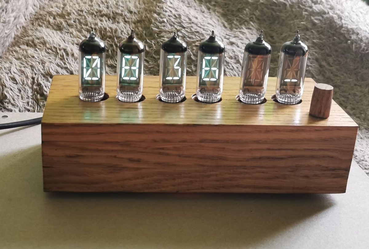
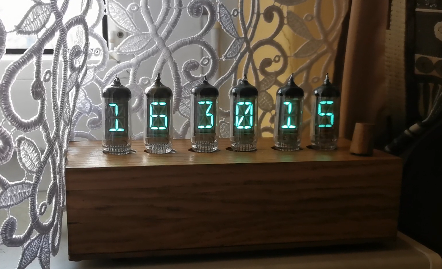
In addition to photos of the clock's elements, I am posting a short video of the clock's operation (the option to display time + weather data is visible). Unfortunately, the photos and the video do not fully reflect the color and smoothness of the animation (no flickering is visible in real life) :(
Additionally, in the attachment *.bin batch for STM32F103C8T6.
Summary
The basic cost is the lamps, approx. PLN 100, the cost of making the plates PLN 100, the rest of the elements max. PLN 100. Total PLN 300, but of course another clock like this would cost PLN 150. The only thing that would still be equally difficult would be the work/adaptation of the wooden housing to the electronics.
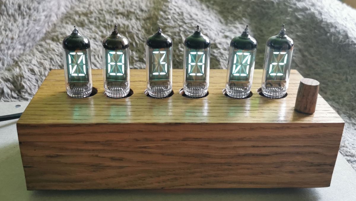
The optical impressions of the working clock on 6 IV17 lamps, as for me, visually pierce the IV18 lamp. Larger numbers, more complex shapes, the possibility of mini-animation. Of course, the hypnotic/calm turquoise VFD color is unchanged :)
Designing and building the clock took me several months in 2022, and this post is the end of my VFD adventures started by the clock on IV18 in 2020.
Attachments:
IV4clock.bin(10.78 KB)
You must be logged in to download this attachment.
ramka_28_B.txt(814 Bytes)
You must be logged in to download this attachment.
About Author
wojo1971 wrote 40 posts with
rating 100 .
Live in city Bielsko-Biała.
Been with us since 2006 year.
Great design! Congratulations! Write to me with a parcel locker for a gift for the presentation! [Read more]
pikarel
09 Mar 2023 13:30
Exemplary design, exemplary prototype execution, clear description with tips.
However, I miss what every digital clock should have: a display panel with a contrasting filter and masking the assembly of... [Read more]
CosteC
09 Mar 2023 21:08
Insanely neat design. Well made from the schematic to the case. Just more of these.
And I have a soft spot for VFD. The blue LEDs are so primitive, even rude. [Read more]
KJ
09 Mar 2023 23:43
Very interesting lamps - nice workmanship, but I do not fully understand this three-layer sandwich, it could be fitted on one pcb and the housing would be much lower. And building a converter on MC34063... [Read more]
CosteC
10 Mar 2023 06:46
Do you have any replacement with similar functionality and price only 2x higher? Available for purchase, of course.
@wojo1971, C22 should be up to 5V. Where it is, it disables the key overload prote... [Read more]
wojo1971
10 Mar 2023 09:16
In the initial phase of the project, before the tests on VFD tubes, I launched a prototype DC-DC converter on the LM2577, it worked properly, nicely kept Uwy about 50 V under load. The problem is that... [Read more]
szeryf3
10 Mar 2023 09:37
Nice description of the project, the execution itself is also nice. [Read more]
CosteC
10 Mar 2023 09:46
Few people understand exactly how the MC34063 works. I am not surprised, because the documentation is full of contradictions and errors. In addition, it is made in old technology and is slow. This causes... [Read more]
pikarel
10 Mar 2023 14:14
The MC34063 works as it should if the power supply that uses it is designed according to the art of design. Even test layouts should be made on a PCB with an appropriate topology of paths, all test spiders... [Read more]
pawelr98
10 Mar 2023 20:35
MC34063 has one advantage, it is cheap. This is where the advantages end because it has no other advantages.
When the power supply is above 5V, then the UC3843 may just be of interest. And this is not... [Read more]
CosteC
10 Mar 2023 21:16
MC34063 works in any topology (buck, boost)
The MC34063 has a high side current measurement which is more versatile than low side and works with over current key protection.
MC34063 can be purchased... [Read more]
Gizmoń
10 Mar 2023 21:53
It's worth thinking about blanking the zero in the tens hour counter, because - although the numbers are really nice - 8 38 02 is clearer than 08 38 02. By the way, I see a nice mix on this CD! It... [Read more]
wojo1971
10 Mar 2023 22:18
The presentation of digital time, e.g. in a Casio watch, is also with an insignificant zero on the hours, but it's a matter of taste 🙂
As for placing the inscription in Cyrillic, I did pcb before... [Read more]
Gizmoń
11 Mar 2023 00:07
I didn't mean the Cyrillic alphabet - I have no prejudices against those letters - but about its combination with English and Polish descriptions, and on one board. It's rare to see such an "international"... [Read more]
pawelr98
11 Mar 2023 01:04
Buck on 34063 is even worse archaism, because the efficiency is already low.
In the boost topology, this chip defends itself only thanks to the external mosfet transistor glued as a "prosthetic".
At... [Read more]
CosteC
11 Mar 2023 07:27
@pawelr98 - you didn't propose anything more universal than MC34063. High efficiency is not always needed. And if I need a high-efficiency boost, I'll take something better than the old UC384x... [Read more]
Mikrob
04 Apr 2023 02:34
And here a colleague would be surprised how many devices these systems still work in, ICL 7006, 7107 etc. are even older and still very popular and reliable [Read more]
KJ
04 Apr 2023 03:22
Just because they work doesn't mean it makes technical sense. Just like the fact that someone drives a Trabant every day does not make a Trabant a good car :D [Read more]
TL;DR: A DIY STM32F103-driven VFD clock powers six IV-17 tubes with a 45 V/400 mA supply; “MC34063 works in any topology” [Elektroda, CosteC, post #20480015] Build cost ≈ PLN 300 and uses three modular PCBs for easy tube swaps.
Why it matters: The project shows how to merge retro VFD aesthetics with modern MCU accuracy and low-cost power design.
What makes the IV-17 tube attractive compared with the IV-18 used previously?
IV-17 is an 18-segment alphanumeric VFD with larger characters and supports mini-animations, while IV-18 is a simpler 7-segment style. Six IV-17 tubes give 108 segments, delivering more detail and a “hypnotic turquoise” look [Elektroda, wojo1971, post #20476772]
Why did the designer still choose the old MC34063 controller in 2023?
MC34063 costs only a few złoty, works from 3–40 V, supports buck or boost topologies, and includes high-side current sensing with internal 1.5 A switch [Elektroda, CosteC, post #20480015] Efficiency was not critical; the 45 V rail draws <1 W, so newer ICs offered little benefit [Elektroda, CosteC, post #20480399]
How is the 45 V supply built safely?
Use MC34063 in boost mode with a 120 µH, >1 A inductor. 2. Add an external IRL540 MOSFET to reduce losses. 3. Set feedback for 45 V to extend tube life (datasheet suggests 50–70 V for multiplex) [Elektroda, wojo1971, post #20476772] Edge case: leaving capacitor C22 in the sense path disables over-current protection and risks MOSFET failure [Elektroda, CosteC, post #20478773]
What waveform drives the L9110 bridge that flips filament polarity?
The STM32 Timer1 outputs complementary 50 %-duty PWM at ~102 Hz. Each half-cycle the L9110 swaps polarity, eliminating cathode poisoning and hum while keeping the RMS filament voltage at 2.4 V [Elektroda, wojo1971, post #20476772] (L9910 in the later post is a typo; part used is L9110.)
How are the 18 segments of each tube addressed?
An HV5812 shift register receives serial data from the STM32F103 and drives all 18 anode lines at 45 V. Six NPN-PNP transistor pairs select the active grid, enabling 6-way multiplex. Discharge resistors of 220 kΩ per line speed blanking [Elektroda, wojo1971, post #20476772]
How is timekeeping accuracy maintained?
The internal RTC uses a 32.768 kHz crystal. Two software trim stages let the user enter 24-hour and 14-day error corrections via the encoder menu, compensating typical ±20 ppm drift to <1 ppm after calibration [Elektroda, wojo1971, post #20476772]
The case is three 17 mm oak planks glued into a block, drilled for PCBs and 20 mm tube windows, sealed with shellac, and closed with 3 mm fibreboard [Elektroda, wojo1971, post #20476772]
Where can I source IV-17 tubes today?
The author bought them on eBay as a bulk order in 2018 [Elektroda, wojo1971, post #20528499] Current listings still appear, but prices vary; expect €3–5 per NOS tube (typical eBay search, 2024).
Is there a quick way to define custom characters on the 18-segment display?
Map ASCII codes to 18-bit patterns stored in a lookup table inside Flash. Send the pattern to HV5812 each refresh cycle. The author spent “some time” perfecting the glyphs but shares a ready-to-flash .bin in the thread [Elektroda, wojo1971, post #20476772]
How power-hungry is the finished clock?
Measured consumption is about 2 W: 45 V × 40 mA anodes plus 2.4 V × 300 mA filaments and MCU overhead (statistic) [Elektroda, wojo1971, post #20476772] A modern SMPS at 80 % efficiency raises wall draw to ≈2.5 W.
3-step how-to: designing a quick MC34063 boost for VFD
Pick Vout (45 V) and Iout (40 mA); calculate L using 72 kHz formula in datasheet. 2. Select Rsense for 1 A peak; use an external logic-level MOSFET for >40 V. 3. Add fast diode and 100 µF/100 V output cap, then test under full multiplex load [MC34063A Data Sheet].
Summary generated by AI based on the discussion content.


Comments
Great design! Congratulations! Write to me with a parcel locker for a gift for the presentation! [Read more]
Exemplary design, exemplary prototype execution, clear description with tips. However, I miss what every digital clock should have: a display panel with a contrasting filter and masking the assembly of... [Read more]
Insanely neat design. Well made from the schematic to the case. Just more of these. And I have a soft spot for VFD. The blue LEDs are so primitive, even rude. [Read more]
Very interesting lamps - nice workmanship, but I do not fully understand this three-layer sandwich, it could be fitted on one pcb and the housing would be much lower. And building a converter on MC34063... [Read more]
Do you have any replacement with similar functionality and price only 2x higher? Available for purchase, of course. @wojo1971, C22 should be up to 5V. Where it is, it disables the key overload prote... [Read more]
In the initial phase of the project, before the tests on VFD tubes, I launched a prototype DC-DC converter on the LM2577, it worked properly, nicely kept Uwy about 50 V under load. The problem is that... [Read more]
Nice description of the project, the execution itself is also nice. [Read more]
Few people understand exactly how the MC34063 works. I am not surprised, because the documentation is full of contradictions and errors. In addition, it is made in old technology and is slow. This causes... [Read more]
The MC34063 works as it should if the power supply that uses it is designed according to the art of design. Even test layouts should be made on a PCB with an appropriate topology of paths, all test spiders... [Read more]
MC34063 has one advantage, it is cheap. This is where the advantages end because it has no other advantages. When the power supply is above 5V, then the UC3843 may just be of interest. And this is not... [Read more]
MC34063 works in any topology (buck, boost) The MC34063 has a high side current measurement which is more versatile than low side and works with over current key protection. MC34063 can be purchased... [Read more]
It's worth thinking about blanking the zero in the tens hour counter, because - although the numbers are really nice - 8 38 02 is clearer than 08 38 02. By the way, I see a nice mix on this CD! It... [Read more]
The presentation of digital time, e.g. in a Casio watch, is also with an insignificant zero on the hours, but it's a matter of taste 🙂 As for placing the inscription in Cyrillic, I did pcb before... [Read more]
I didn't mean the Cyrillic alphabet - I have no prejudices against those letters - but about its combination with English and Polish descriptions, and on one board. It's rare to see such an "international"... [Read more]
Buck on 34063 is even worse archaism, because the efficiency is already low. In the boost topology, this chip defends itself only thanks to the external mosfet transistor glued as a "prosthetic". At... [Read more]
@pawelr98 - you didn't propose anything more universal than MC34063. High efficiency is not always needed. And if I need a high-efficiency boost, I'll take something better than the old UC384x... [Read more]
And here a colleague would be surprised how many devices these systems still work in, ICL 7006, 7107 etc. are even older and still very popular and reliable [Read more]
Just because they work doesn't mean it makes technical sense. Just like the fact that someone drives a Trabant every day does not make a Trabant a good car :D [Read more]
Where did you buy the lamps? [Read more]