 .
.
Hello
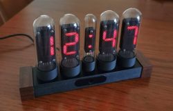
I present another watch from my collection.
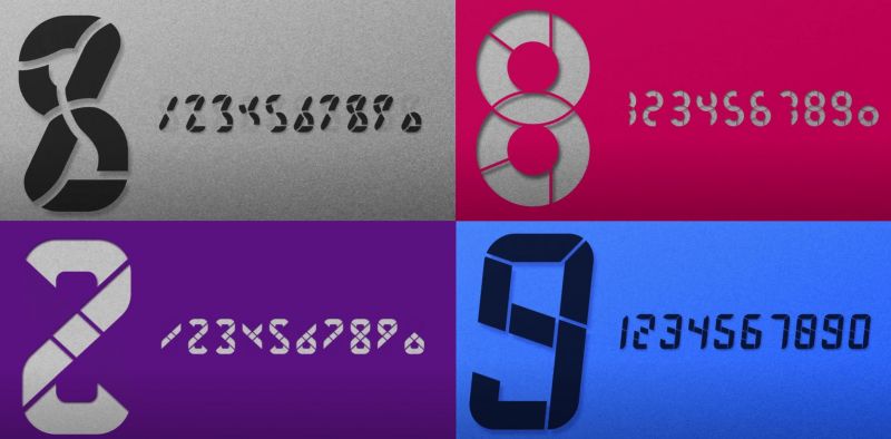
I got a bit bored with the blocky shapes and came up with something like this.
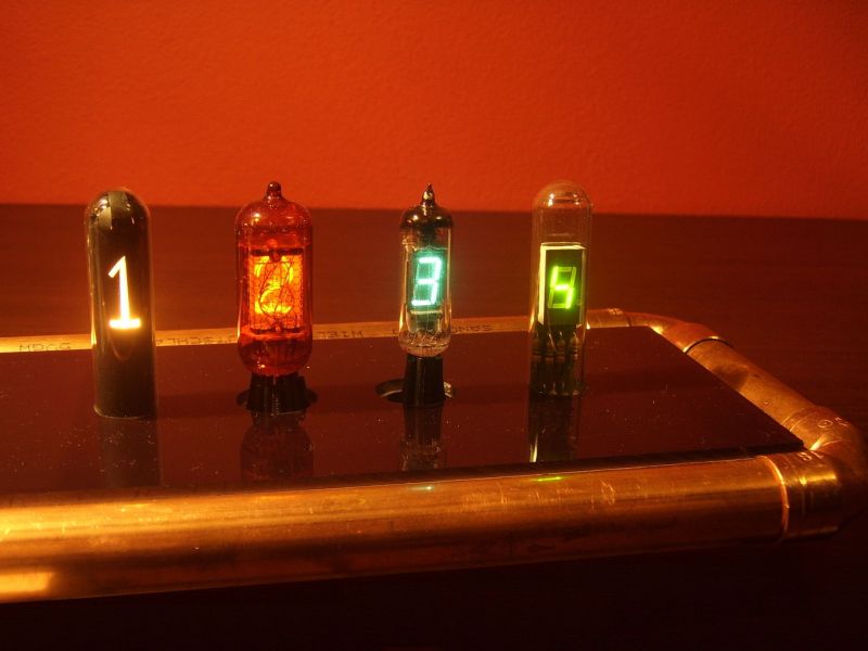
We all have a fascination with tube displays from a bygone era, unfortunately their prices are a bit prohibitive and basically nothing can replace them. The aim of the project was to get at least a minimal approximation to the atmosphere of tube displays. All in all, what came out was quite an unusual creation
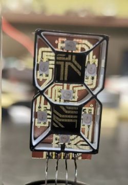
The SK6812 mini-E LEDs (2.8x 3 mm) were used in the design, due to the small size of the display. These LEDs can be addressed similarly to the WS2812. This of course limited the number of wires connecting a single display to 4.
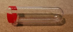
Most of the components were printed. I obtained the glass bulbs from tubes with a diameter of 25 mm. I also looked for a larger diameter, but further down the line it's all bottles and jars.
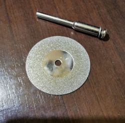
I cut the test tubes to a length of 80 mm. Cutting with a mini grinder with a diamond disc. First a scratch all round and then 2-3 rounds are enough.
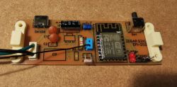
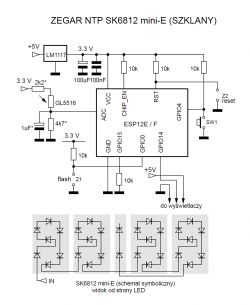
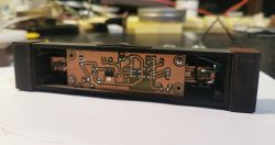
The electronics are a handful of components. At its heart is the ESP8266. The displayed time is taken from NTP servers.
 .
.
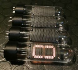
Prototype displays. Digit height 30 mm. I tried to simulate a getter, but without success.
 .
.
Description of the build.
Prints from FDM printers do not look sensational. To make a printed solid look nice, further processing is needed.
Base:
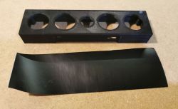
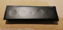
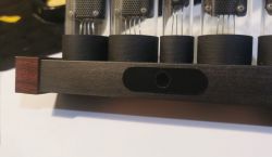
I start machining the base by applying adhesive film to the top of the panel.
 .
.
The surface area is not too large, so there were no problems.
 .
.
After gluing, I trimmed the foil roughly along the contour of the base. I start sanding from the folded edge - front-top and sides-top, until the excess foil is rubbed off.
When sanding the front and sides, you need to pay attention to the edge of the adhesive film and break down the edge every so often.
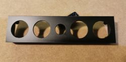
After sanding the front, I cut out the holes with a knife.
 .
.
The front is grey after sanding. To restore the colour, it is wiped with a cloth moistened with liquid silicone. In my opinion, the final looks better than the filament thread.
 .
.
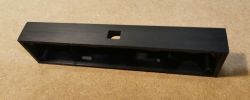
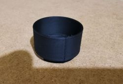
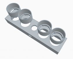
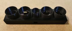
You can now paste the plinths as shown, paying attention to the cut-outs inside the plinth and its seam so that it is at the back.
 .
.
You can direct the seam towards adjacent plinths. But this is a choice of slicer settings.
 .
.
 .
.
Mounting displays:
I bent the LED leads down before mounting.
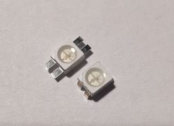 I have bent the LED leads down before mounting.
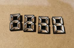
The fenders of the digits are covered with white veneer for better light diffusion. They can also be painted.
 .
.
The components of the digit housing.
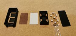 .
.
Order of assembly. All elements are assembled with a snap (no glue).
The back cover can be printed in white or transparent plastic. This results in a slight glow on the back of the watch.
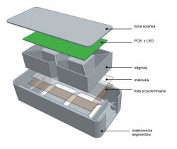 .
.
Assembled numerals.
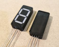 .
.
The cover mesh needs to be pre-matched with the display switched on before it is cut to size in order to select the optimum position of the holes in relation to the display segments.
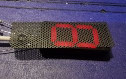 .
.
Mounting .
Test before final assembly. Colour rendering poor unfortunately as it is on film....
Soldered to the PCB, the displays are mounted from the bottom of the panel. Simply slide them in.
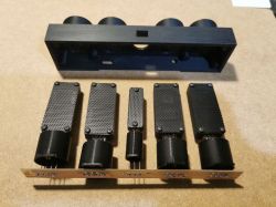 .
.
There is no fixing here.
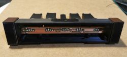 .
.
Finally, a mother board is attached to press down the display PCBs.
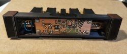
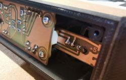 .
.
The plinths of the 'tubes' have a slight play due to the spread in diameter of the tubes. In order to make the slides "sit" tightly I used insulating tape.
 .
.
Scheme:
 .
.
Cutting the tube: The cut section is not even 10mm. To make it more difficult
Other comments: .
PCB of digits and colon - 0.6mm thick. Other 1mm.
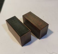
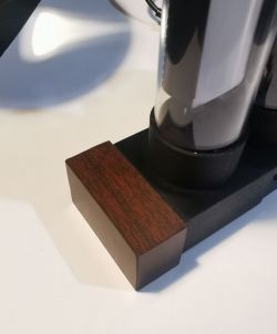
A description of the woodgrain sides is a few posts below.
All elements printed with PLA on glass with 0.4mm head.
I used two slicers. Cura 4.13.0 and Prusa 2.8.1
ArduinoIDE source code, STL and pdf files of the PCB for thermal transfer are attached.
Well, and I think that's all there is to it. Greetings
Cool? Ranking DIY


 .
.
