logo elektroda
logo elektroda
X
logo elektroda

Power amplifier on NE5532 - ty.ytka

tytka  79 21117 Cool? (+61)
📢 Listen (AI):

TL;DR

  • A stereo power amplifier built from NE5532 operational amplifiers replaces a conventional power stage with an op-amp-based experiment.
  • Each channel uses four op-amps in the voltage stage, 64 op-amps in parallel as the output buffer, and one op-amp for DC-servo control.
  • The supply is stabilized at +/-18 V with LM338 regulators, and speaker protection uses a uPC1237 circuit.
  • The finished amplifier delivers 2×14 W into 8 ohms and sounds detailed, clean, and surprisingly strong in the bass.
  • Cooling matters, because the regulators dissipate a lot of heat and the op-amps reach about 45-50°C during operation.
Generated by the language model.


It may seem ridiculous, but you can build an interesting power amplifier from ordinary operational amplifiers (with the right amount of them). :)

From this "miracle" I achieve 2×14 W on a load of 8 ohms. Maybe this value is not shocking, but considering what we get it from, it's probably not a little bit.

First things first.
This project was created only as an experiment, made out of curiosity.
The source of inspiration for this project was an article by Douglas Self in the Elektor magazine (issues 10 and 11 of 2010). Whereas the design of my headphone amplifier ( link ) served as a fitting for this very crazy project.

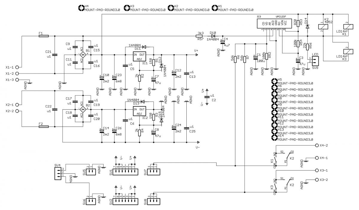
However, my project is not an exact copy of the mentioned article. I simplified it a bit in my experiment. I resigned from balanced inputs and the possibility of connecting both channels into a bridge. I made the security system on uPC1237, and the stabilizers on LM338.

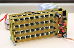
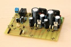
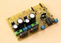
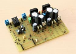
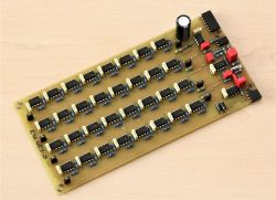
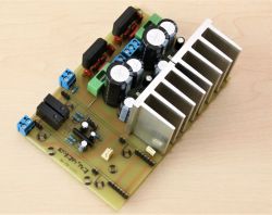
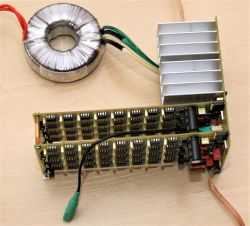
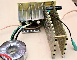
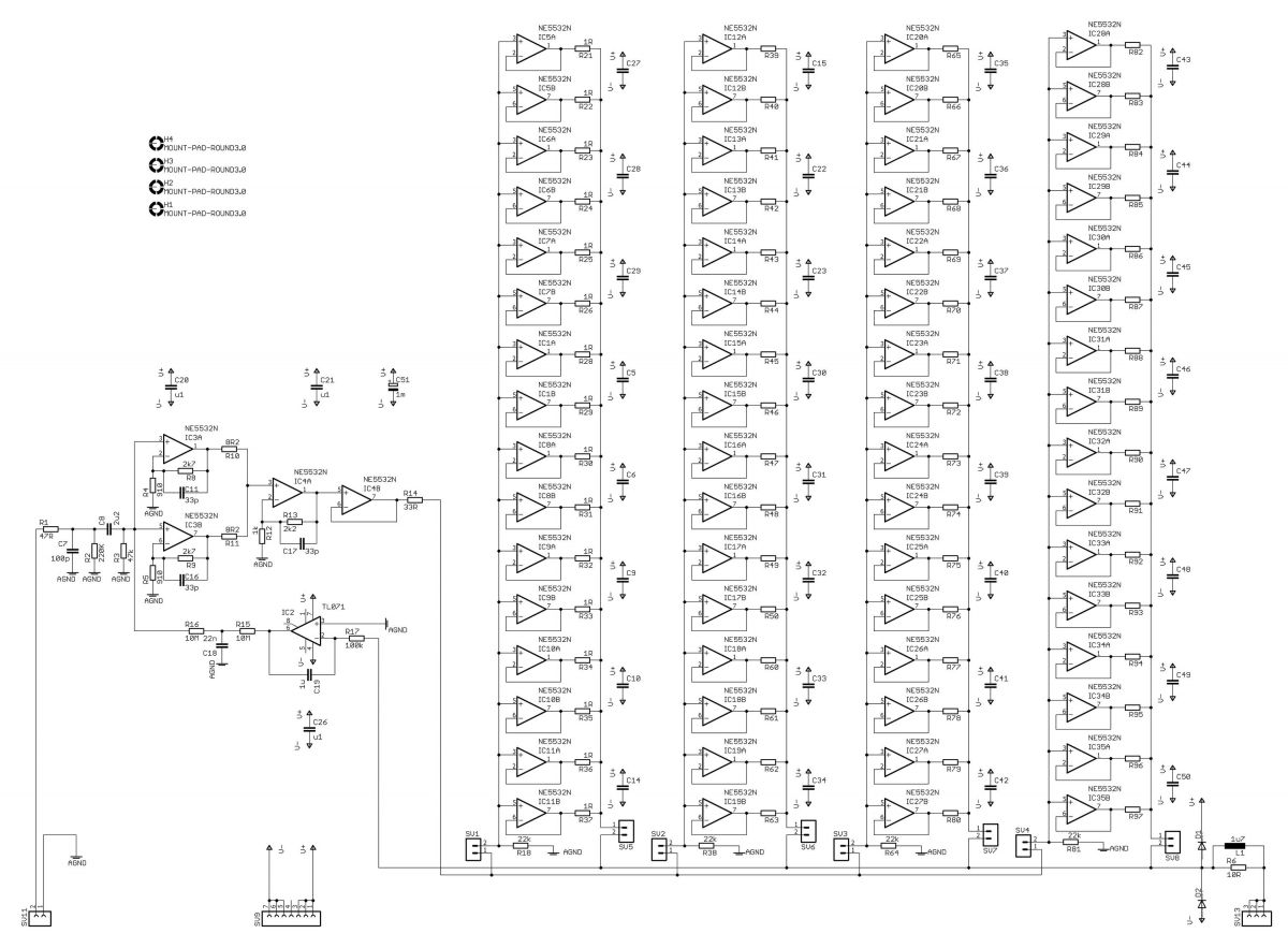
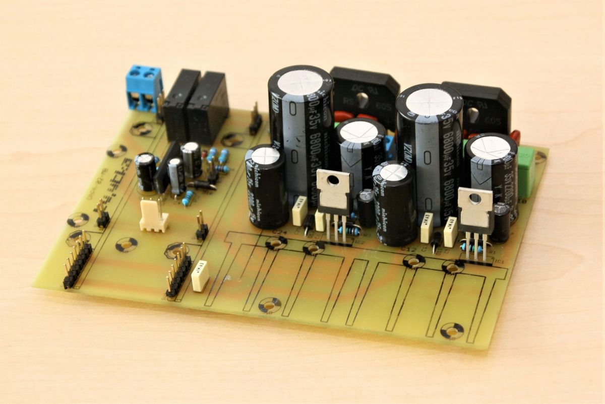
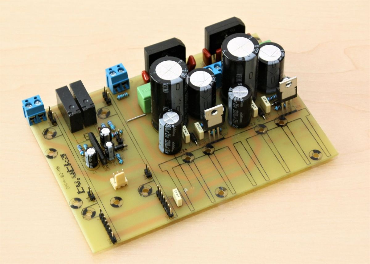
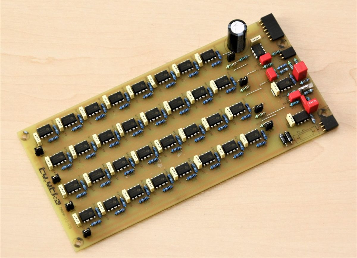
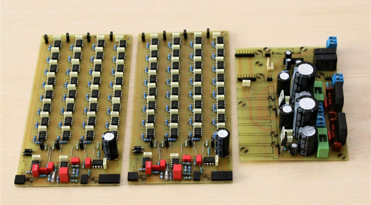
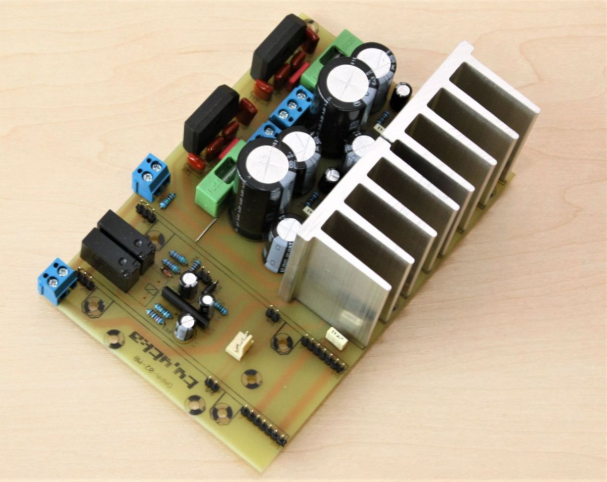
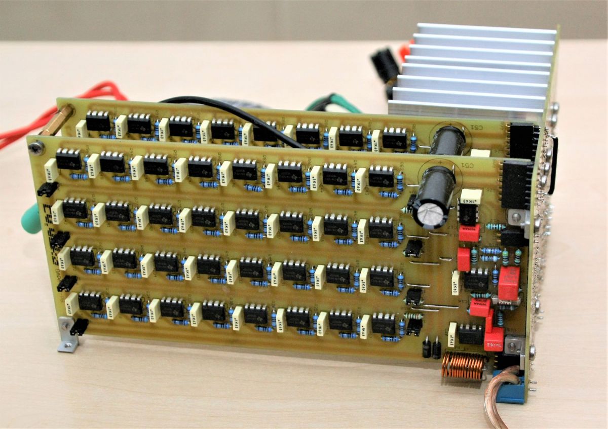
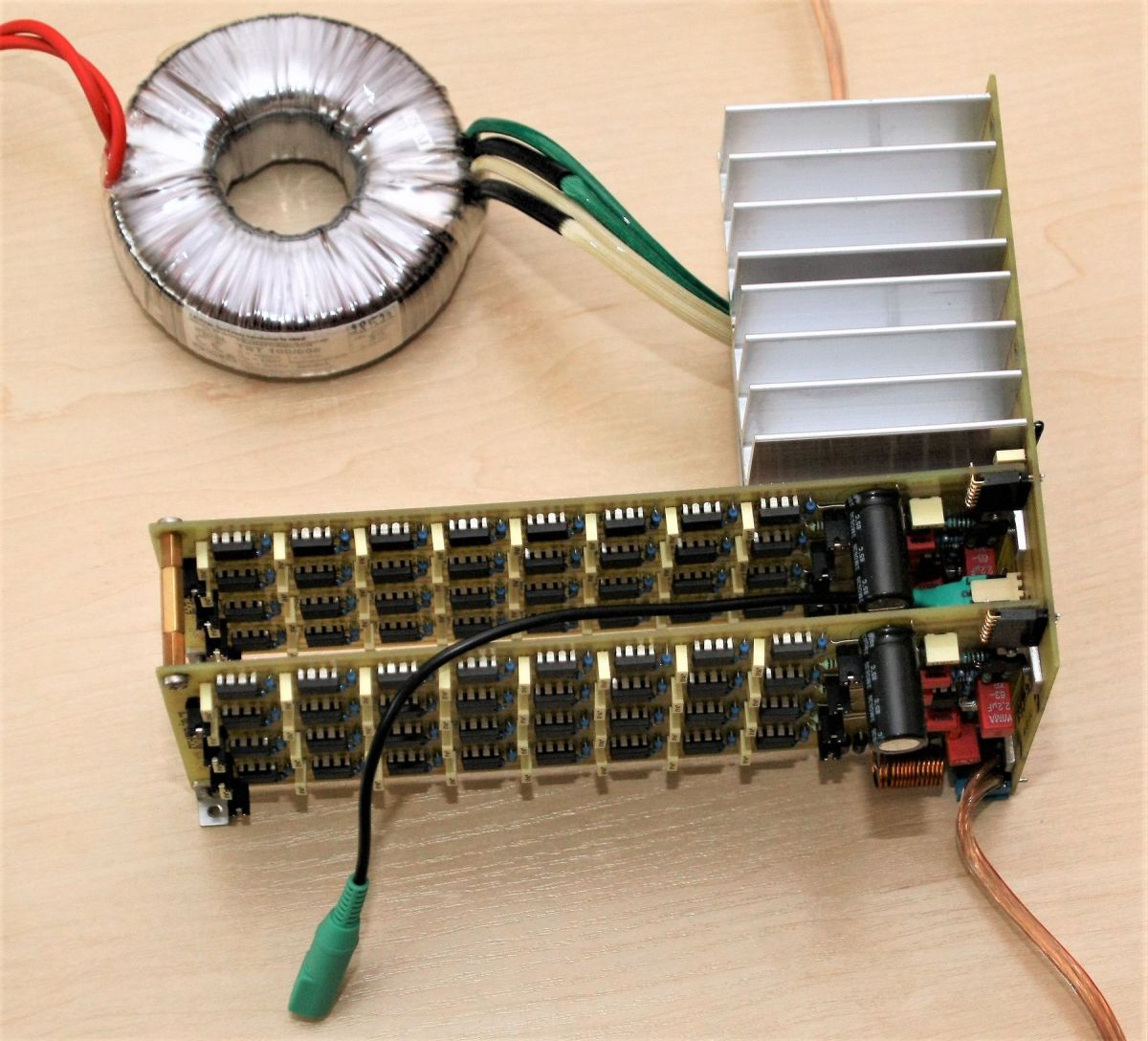
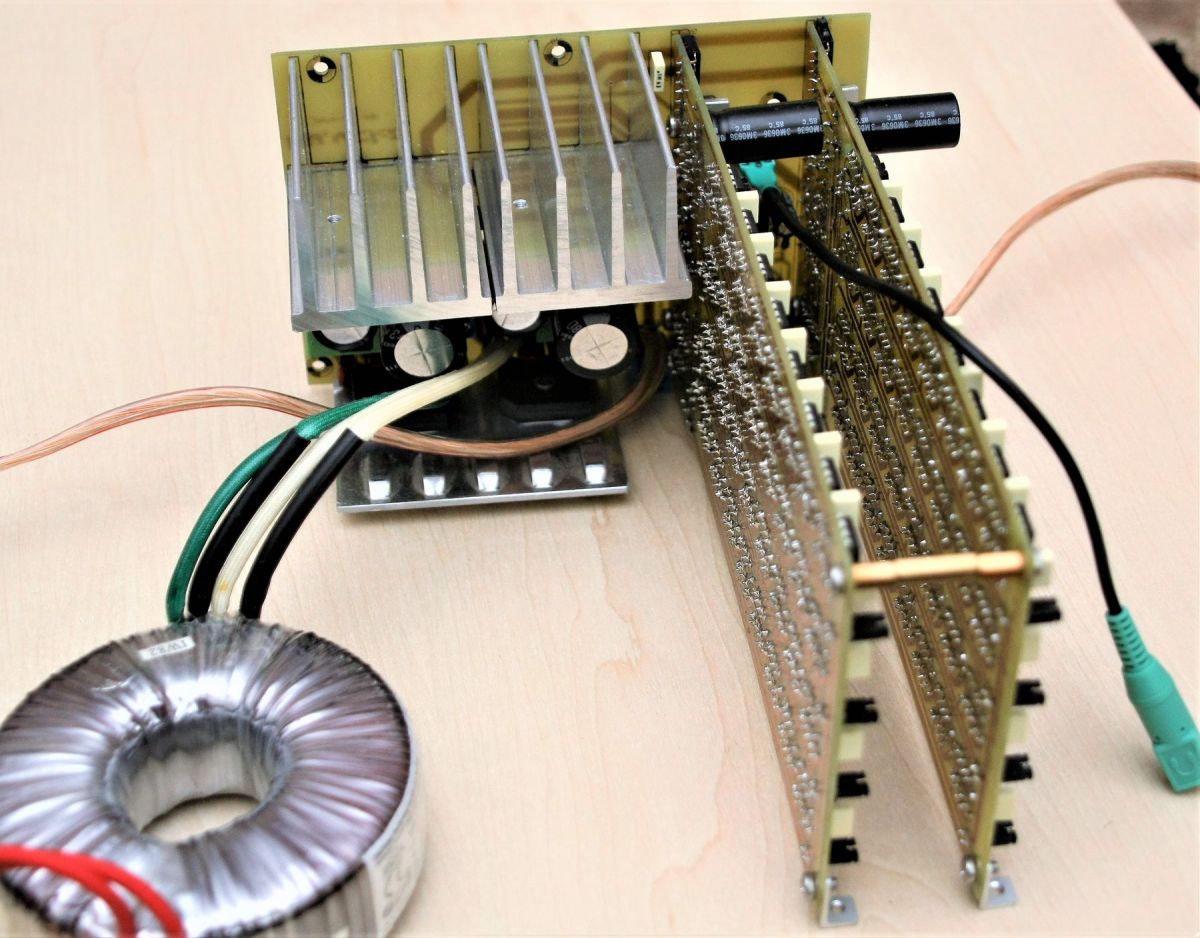
I assembled the whole amplifier on three boards. One containing stabilized power supplies, supplying +/-18 V, and a loudspeaker protection system. The other two contain amplifiers for each channel. Each channel contains 4 operational amplifiers in the voltage amplifier part, 64 operational amplifiers connected in parallel working as an output buffer and one op-amp operating in the DC-servo system.

Tile schemes:


A few photos of the assembled layout:


Now maybe a few words about the impressions of the final effects.
Overall, I perceive the amplifier very positively from the listening point of view. The presented sound is quite detailed, clean without coloration. I was surprised by the quality of the bass, but in my opinion it is due to the quality of the power supply (stabilizers).

For now, I do not plan to use this project for a specific purpose, but I also do not rule it out in the future. However, it is quite interesting in terms of sound.
However, if someone wanted to use something like this for a specific purpose, remember to ensure proper cooling. Unfortunately, the stabilizers have to dissipate quite a lot of heat, and even the operational amplifiers themselves heat up to about 45-50 degrees Celsius during such operation.

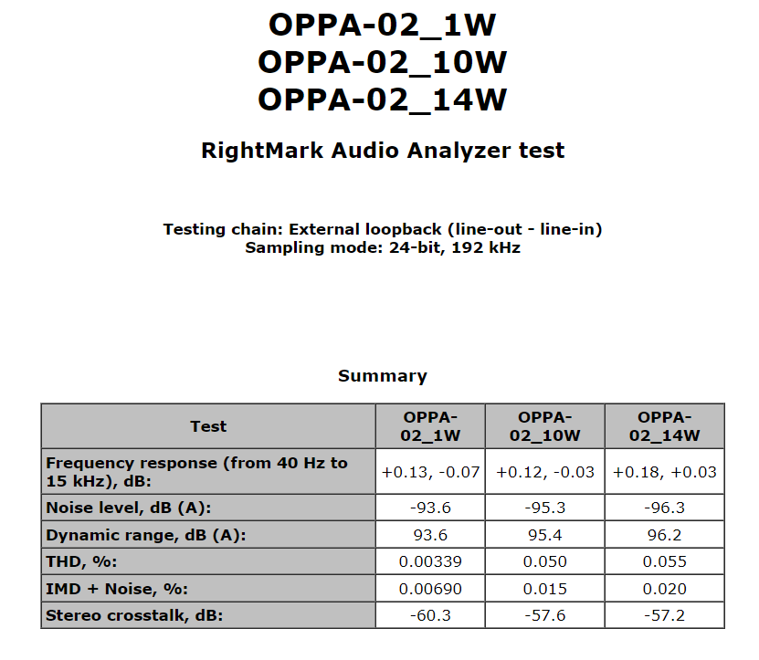
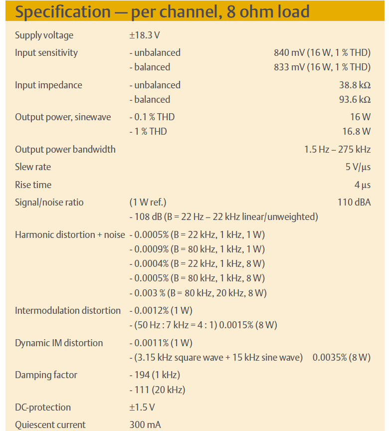
Something about parameters.
Output power with simultaneous control of both channels - 2×14W on 8 ohms .
Other parameters are presented in the table below. Values for three different output powers 1W, 10W and 14W .


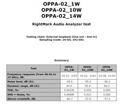
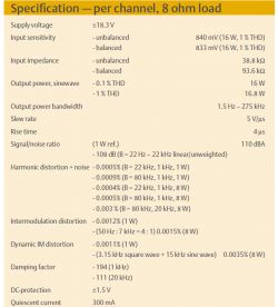
The author of the article mentioned at the beginning achieved slightly different parameters in his experiment:


The differences in the obtained parameters could have been influenced by the simplification of my system and the fact that I used the cheapest version of NE5532, because " P ".

About Author
tytka
tytka wrote 760 posts with rating 1836 , helped 8 times. Live in city Pabianice. Been with us since 2006 year.

Comments

marweg1967 04 Jul 2023 02:43

I read that article some time ago (although not in Elektor) and I was very interested in it. So much so that I also decided to implement this seemingly crazy project someday. Unfortunately, the word "someday"... [Read more]

rb401 04 Jul 2023 04:12

The concept seems older than 2010 to me. Your performance is very nice. I also like that you managed on a single-sided PCB. Such a curiosity. Recently, on Aliexpress, I also came across several such... [Read more]

mkpl 04 Jul 2023 07:24

Overall nice but for the fan and for fun. What did you measure with? Do you have a card reference measurement? Because you don't know where the measurement limits are. The second thing, do you have... [Read more]

tytka 04 Jul 2023 08:36

I also found similar modules on Aliexpress. Only they break everything into mini-blocks. Those boards that colleague rb401 pointed out are the output buffers themselves. They even offer such little things: ... [Read more]

Urgon 04 Jul 2023 10:54

AVE... This is a very well made design, and an interesting concept, although usually parallel connection of operational amplifiers is practiced in order to reduce noise in ultra-sensitive measuring amplifiers.... [Read more]

katakrowa 04 Jul 2023 19:35

Considering that for 5 USD we can buy 100 pieces of NE5532 in SMD, the project makes quite a lot of sense. [Read more]

Urgon 04 Jul 2023 19:47

AVE... The only question is, are these cheap NE5532 originals or Chinese clones? If they are clones, do they therefore keep their parameters? [Read more]

gulson 04 Jul 2023 20:08

Very interesting design, that's what DIY is for! Write to me in a parcel locker and I will be happy to send you a gift. [Read more]

tytka 04 Jul 2023 22:34

Here is the promised reference measurement of the card used for the measurements: https://obrazki.elektroda.pl/2831165000_1688501807_thumb.jpg And as for the price with the NE5532 used. As I mentioned,... [Read more]

pikarel 05 Jul 2023 15:20

This is real DIY, in an exemplary execution; that's what the DIY department is for. Now we are waiting for posts that will expose "non-compliance of the device made with the standards", buddy @tytka... [Read more]

austriackimalarz 05 Jul 2023 16:04

Who was calling me? ;) I really like this experiment. Generally, connecting several amplifiers in parallel eliminates noise, but ... without exaggeration ;P Maybe it's worth using amplifiers in SOT23-5... [Read more]

lechoo 05 Jul 2023 21:52

Can you reveal what you modified in UMC202HD to get such good parameters? [Read more]

rb401 05 Jul 2023 21:55

I strongly warn against using these cubes and others from the LM321, 358, 324 group in this construction. It's just that in these amplifiers, in applications where the output current changes direction,... [Read more]

tytka 05 Jul 2023 22:09

@lechoo I limited the input path of this card to a minimum, because as it turns out, the factory Midas input amplifiers are a total flop and the reason for the imperfection of this card. I described my... [Read more]

marweg1967 06 Jul 2023 01:36

Will your colleague reveal details about this security? Input diodes? Because this Behringer really hums badly and I'm getting ready to etch the board to use the workaround described by a colleague... [Read more]

kamil.b 06 Jul 2023 14:09

It is conceptually similar to this project: Headphone amplifier based on NE5532 Quite a neat design (both the author's and Phil's from the movie) [Read more]

austriackimalarz 06 Jul 2023 20:29

Thanks for the information, I didn't know about that. I'm thinking... Let's give 4 sets of amplifiers powered from +-22V, let's connect them into 2 separate bridges. This would give 44Vpeak,... [Read more]

rb401 07 Jul 2023 00:20

This cube is basically the same as the LM358 and has the same characteristic of these specific distortions as this whole family. So it is definitely not suitable for this construction. [Read more]

austriackimalarz 07 Jul 2023 00:47

This generally looks like a feature of BJT-based amplifiers. Versions based on JFET transistors do not have such problems. [Read more]

FAQ

TL;DR: “It sounds quite detailed,” and the builder measured 2×14 W into 8 Ω from a power amplifier made with parallel NE5532 op-amps. This FAQ helps DIY audio builders understand the topology, measurements, thermal limits, part choices, and why this experiment works despite its obvious inefficiency. [#20640831]

Why it matters: This thread shows how a seemingly impractical op-amp array can become a usable audio power stage, while exposing the real limits in cooling, idle power, measurement method, and device selection.

Option What the thread says Main trade-off
NE5532P Used in the featured build; 2×14 W into 8 Ω; praised for clean, detailed sound Higher chip count and heat [#20640831]
TL07x Considered for very large SMD builds; lower current per amp in some variants Questions about output resistance and suitability [#20654388]
LM833 Mentioned as sonically stronger than TL07x in listening tests Not developed into a full build here [#20657278]
LM358/LM324/LM2904 family Explicitly warned against for this push-pull output use Output crossover “dead” zone harms performance [#20643524]

Key insight: Paralleling op-amps can lower noise and raise output current, but in this thread the limiting factors were not headline wattage. They were idle dissipation, regulator heat, measurement method, and the output-stage behavior of the chosen op-amp family.

Quick Facts

  • The finished amplifier used three boards: one PSU/protection board with ±18 V rails, plus two channel boards; each channel had 4 op-amps in voltage gain, 64 op-amps in parallel as the output buffer, and 1 op-amp for the DC-servo. [#20640831]
  • The builder reported 2×14 W into 8 Ω with both channels driven, and the op-amps themselves reached about 45–50 °C during operation, so cooling was identified as mandatory for practical use. [#20640831]
  • The chosen parts were TI NE5532P devices bought from TME for under 1.9 gross per piece at the project quantity, which kept the experiment financially plausible despite the large chip count. [#20642244]
  • A later large-scale variant showed the thermal penalty clearly: 250 TL072 packages connected in parallel per block drew about 1 A at ±18 V at idle, meaning a 1000-op-amp amplifier could waste roughly 60 W before delivering signal. [#20840893]

How was this NE5532 power amplifier built to deliver 2×14 W into 8 Ω using so many op-amps in parallel?

It used many small op-amp stages to share the output job. Each channel had 4 op-amps in the voltage amplifier, 64 op-amps in parallel as the output buffer, and 1 more op-amp for the DC-servo. A separate board provided stabilized ±18 V rails and loudspeaker protection, and the whole amplifier was split across three PCBs. The builder simplified the original Elektor-inspired concept by removing balanced inputs and bridge mode, then measured 2×14 W into 8 Ω with both channels driven. [#20640831]

What is a DC-servo in an audio power amplifier, and why was an extra op-amp used for it in each channel?

A DC-servo is a control circuit that corrects output DC offset without putting a large capacitor in the audio path. The builder used one extra op-amp per channel for this function, separate from the 4 gain-stage op-amps and the 64 parallel output devices. “DC-servo” is an audio correction circuit that monitors slow DC error at the amplifier output, injects a compensating signal, and keeps the speaker near 0 V without altering normal audio-band gain. That choice fits a design built for direct-coupled listening tests. [#20640831]

Why does paralleling dozens of NE5532 op-amps reduce noise, and how does that differ from using them to increase output current?

Paralleling op-amps reduces equivalent input noise by averaging many uncorrelated noise sources, while also letting many outputs share load current. One commenter quantified the noise effect: with N devices in parallel, noise voltage falls by √N, so 2 TL071s drop from 15 nV/√Hz to 10.6 nV/√Hz, and 2000 devices reach about 0.335 nV/√Hz. The same topology can also raise output current, but another commenter stressed that noise reduction is the classic reason for this technique, not power drive. [#20654463]

What measurement setup was used for this amplifier, and how do asymmetrical and differential load measurements change the results?

The amplifier was measured asymmetrically, not differentially, and that matters. One commenter warned that asymmetrical measurement creates a ground loop through the interface output, amplifier, load return, and interface input ground. He reported that switching configuration improved the noise result from 102 dB dynamic range to 110 dB. A practical check is: 1. measure the audio interface alone, 2. compare asymmetrical and differential load wiring, 3. confirm where the measurement floor sits before judging the amplifier. [#20641108]

How was the Behringer UMC202HD modified to get better reference measurements, and what was wrong with the stock Midas input stage?

The interface was modified by stripping the input path down to a minimum because the stock Midas input amplifiers were described as the main weakness. The builder said those factory input amps were “a total flop” and the reason the UMC202HD underperformed as a measurement front end. After the modification, he also added input protection because he had already burned one AD8694 on the input stage. The thread does not list the full schematic here, but it clearly states the rationale and the failed part. [#20643545]

Where can you buy a working uPC1237 loudspeaker protection IC today, and what risks come with sourcing it from China?

The builder bought a working uPC1237 from China and said that only Chinese sources now seem to produce these chips. He also warned that buying them there involves risk, so the thread treats availability as possible but uncertain. The practical takeaway is simple: you can still source uPC1237-based protection, but expect authenticity and consistency risk when the supply chain is limited to Chinese sellers. [#20641164]

Why do LM321, LM358, LM324, and LM2904-family op-amps perform poorly in this kind of parallel push-pull audio output stage?

They perform poorly here because their output stage can momentarily “die” when output current changes direction. One commenter explicitly warned against LM321, LM358, LM324, and related parts for this topology, and later explained that the problem comes from a push-pull output stage with no quiescent current. That creates a switching interval between the upper and lower transistor, which shows up as distortion. Another commenter then confirmed LM2904AQTH behaves like LM358 in this respect and is therefore unsuitable for this amplifier style. [#20645984]

NE5532 vs TL07x vs LM833 for an op-amp power amplifier: which one makes more sense for sound quality, noise, and current draw?

In this thread, NE5532 is the safest proven choice, TL07x is a scalable experiment, and LM833 is praised mainly on listening quality. The finished amplifier used TI NE5532P and was judged clean and detailed, while one commenter said listening tests gave NE5532 or even LM833 a clear quality advantage over TL07x. For current draw, another large-scale build using TL072 showed the downside clearly: 250 packages per block drew about 1 A at ±18 V at idle. That makes TL07x attractive for packaging experiments, but not automatically for efficiency. [#20657278]

What is damping factor in a loudspeaker amplifier, and why might TL071 or TL072 output-stage resistance reduce it in a parallel op-amp design?

Damping factor is the amplifier’s ability to control speaker motion through low output impedance. One commenter warned that older TL07x-family behavior can add substantial effective output resistance because the final stage includes emitter resistors and another resistor in series with the op-amp output. “Damping factor” is a loudspeaker-control metric that compares load impedance to amplifier output impedance, so a lower output impedance gives tighter electrical control over the driver, especially at low frequencies. In a parallel speaker-driving array, that extra resistance can limit both output power and damping factor. [#20666706]

How do you estimate transformer size, idle power loss, and heatsinking for a large parallel-op-amp amplifier running on ±18 V?

Start with idle current first, because it dominates the thermal budget. In one large TL072 example, 250 packages per block drew about 1 A at ±18 V, so a 1000-op-amp amplifier could waste about 60 W at idle. Another commenter estimated that a stereo bridge design at this scale would need roughly a 400 W transformer, while even a smaller stereo variant could need about 150 W and dissipate up to 90 W in the ICs at idle. That is why the thread repeatedly treats heatsinking and airflow as design requirements, not accessories. [#20841106]

Why did the author use LM338 stabilizers and large output capacitors, and how could 2200 µF on an LM338 output affect regulator performance?

The builder used LM338 stabilizers to create the amplifier’s regulated ±18 V rails and credited the strong bass partly to PSU quality. A later commenter challenged one detail and said 2200 µF on the LM338 output is too large, arguing that it worsens regulator behavior and that 1 µF is enough at the output in this case. So the thread presents both views: the regulated supply helped listening impressions, but very large output capacitance on LM338 may degrade regulator performance rather than improve it. [#20656289]

What is a bridge amplifier configuration, and how would bridging large blocks of TL072 or TL071 op-amps change voltage swing and output power?

A bridge amplifier drives the load from two opposite-phase outputs, doubling voltage swing across the speaker. In the thread, one builder described using two 250-TL072 blocks to form one bridge, then two bridges for stereo. Another commenter estimated about 110 W per channel into 4 Ω in that kind of stereo bridge arrangement and said a transformer around 400 W would then be appropriate. The thread also notes a real limit: output swing loses several volts versus the rails, so bridge power is high but not idealized. [#20841399]

How should you cool a commercial-style version of this amplifier built with SOIC or SMD op-amps on a double-sided PCB?

Mount the op-amps on one side, place the remaining SMD parts on the other, apply thermal paste, and bolt the PCB to a heatsink. That was the specific commercial-style suggestion made in the discussion for a SOIC or SMD version. The idea matters because the original through-hole build already heated the op-amps to about 45–50 °C, and larger arrays showed even worse idle dissipation. The proposed double-sided board turns the whole PCB into a heat-spreading interface instead of relying on free air alone. [#20652784]

What kind of input protection can be added to a modified UMC202HD after burning an AD8694, and how do Zener diodes compare with anti-parallel diode strings or JFETs used as diodes?

The thread points to clamp-style protection, but it does not fully settle the best device choice. The builder said he added protection after burning an input AD8694, then later linked updated information using Zener-based protection. Another commenter said he had expected either anti-parallel strings of 3–4 ordinary diodes or JFETs used as diodes, and asked whether the Zeners added audible noise. The thread records that question, but it does not report a measured noise penalty from the chosen Zener approach. [#20713587]

Which class D op-amp or audio amplifier models already sound indistinguishable from analog in the audio band, as mentioned in the discussion?

No specific class D op-amp or amplifier model was named in the discussion. One commenter claimed such devices already exist today and said they are still single-phase designs switching around 300–500 kHz rather than at megahertz frequencies. When another participant asked for a model number, none was provided in the quoted thread. So the only reliable answer here is that the claim was made, but no concrete product was identified. [#20658147]
Generated by the language model.
%}