Class A amplifier, full Dual Mono
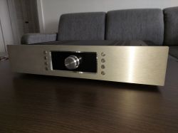
Hello,
By way of introduction:
The amplifier is visually very similar to the Gamut design. It's a coincidence. Wanting to build an amplifier, I was looking for a damaged enclosure donor. The housing of the Koda AV-600X receiver caught my eye, but the knob was asymmetrically placed. I didn't find anything interesting, I started to draw something similar to this pattern myself, but with a symmetrically placed knob. There were many iterations until an almost final form emerged, very similar to the present one. Then I accidentally came across the Gamut DI 150 amplifier and noticed that it looks almost identical to the amplifier in my concept. I began to hesitate whether to change my idea to something else, because it is someone's technical idea, someone's industrial design. I started to study the regulations in this direction and it turned out that the law allows the use of an industrial design for personal use, so a stone from my heart and I started to act.
The inspiration for the new amplifier was the occasional purchase of the Vincent SV-121 amplifier and comparing its sound with my existing amplifier, described in this topic:
https://www.elektroda.pl/rtvforum/topic3780837.html
It turned out that acoustically Vincent is several classes above. Unfortunately, Vincent does not have a signal output, BT and, most importantly, a phono preamplifier.
This is where the search for an interesting scheme, design and construction began.
The amplifier was built for seven months.
Its design consists of separate plates of individual modules, so that you can easily upgrade, upgrade, etc.
Everything was packed into the 1NPD02300B housing purchased from modushop.
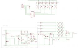
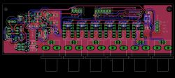
The input selector board is integrated with the phono preamplifier. In the phono preamplifier I used a circuit known from more expensive Pioneer and Denon designs with FET transistors at the input. The sound from this circuit is clearly better than the circuits I've made before (including the Emerald circuit, praised on the web).
The board also has a signal output buffer for driving the previously presented Equalizer on IN-9 tubes.
Scheme and selector board (for one channel) below:
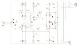
The preamplifier is a slightly modified circuit taken from the following source:
https://www.electroschematics.com/class-a-preamplifier/
Diagram of one channel and board below.
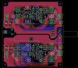
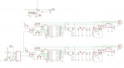
The power amplifiers are based on the Pioneer A-09 scheme, but they have been redesigned to use currently available and cheap transistors. The board has been designed to be screwed together with the transistors on the heat sink.
Below is the schematic and PCB for one channel.


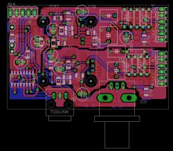
The amplifier additionally has a Bluetooth receiver and a DAC also working in Dual Mono. The DAC board has been designed in such a way that it can be screwed onto the PA214 Bluetooth receiver (bought on a well-known Asian website).
The signal in the SPDIF format is fed from Bluetooth to the DAC board. There, through the 4052 multiplexer, one of the three SPDIF (Coaxial / Optical / Bt) sources is selected, whichthen, through optocouplers, it is fed to SPDIF decoders independent for each channel, and from there to converters.
The "primary" side of the DAC (Bluetooth receiver, selector, Toslink receiver) is powered from the power supply of the digital part, the "secondary" side (SPDIF decoders, converters) - from the output of the audio power supply switched on with a relay.
The DAC is based on the Cirrus Logic CS4334 converters, because they are one of the few that can still be purchased on the market, and they are also easy to use.
Below is the schematic and PCB
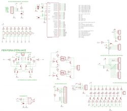
The amplifier's control section is not too complicated and was designed parallel to the front panel to handle the backlight, buttons, have a hole for the potentiometer axis, etc. It is based on the Atmega16 microcontroller.
A 10x5mm model bearing with a flange was fitted into the hole for the potentiometer axis, through which the potentiometer axis with a diameter of 5 mm passes. The bearing is the fulcrum of the axle.
Effects below.
Control board:

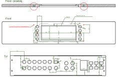
Aluminum front panel of the case:
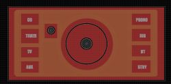
Panel with illuminated inscriptions under the glass (with a cutout for the IR receiver and the axis:
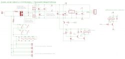
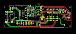
The control section is powered from a stand-by power supply connected to the power transformer switching system and soft-start.
It is presented below:
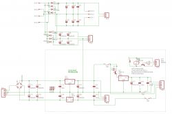
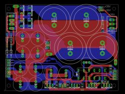
The audio part is powered by the power supply system with independent circuits of power transistors, power stage voltage amplifier and preamplifier. In addition, through the relay, the DAC and BT are powered. The relay turns on only when selecting digital sources, so when playing audio from other sources on the DAC and BT, no voltage is applied.
The audio power supply is shown below and is one of the two channels. The tile of the second channel is a symmetrical reflection.
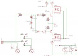
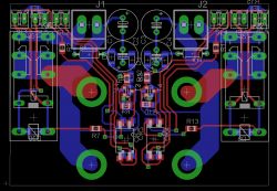
And finally, the speaker protection board. This protection is supervised by the microcontroller that controls the amplifier and is screwed directly to the loudspeaker terminals.
In general, the launch did not cause any major problems. The analog part started right away. only adjustment of the offset, transistor currents was required and it was possible to twist. The mechanical part turned out to be a big problem due to the use of a slightly too small housing. On paper, everything was nice to fold, but in reality it was not so colorful. The housing also required a few modifications, especially the way the radiators were screwed to the frame.
In terms of electronics, I had the biggest difficulties with starting the DAC. The reason was my negligence, because I downplayed the requirement to delay the Reset pin relative to the power supply in the DIR9001 chip. It took me several hours to figure out what the source of the problem is. Using an inertial system on the Reset pin solved the problem.
Below are some photos of the construction.
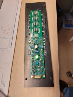
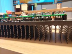
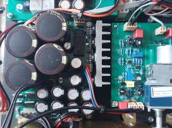
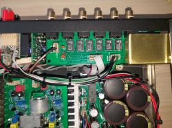
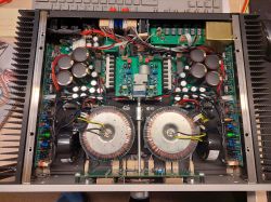
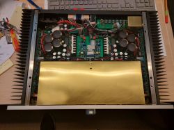
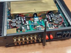
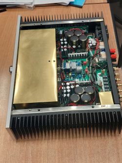
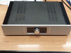
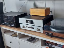
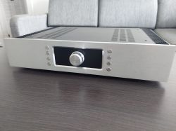
I also add a video showing the operation of the amplifier icon illumination:
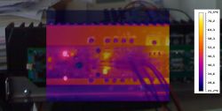
The amplifier, as in class A, heats up mercilessly:
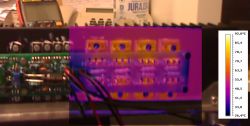
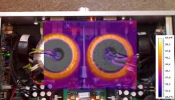
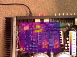
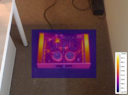
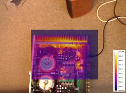
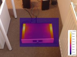
problems
- low brightness of the subtitles backlight - they were etched on the PCB and covered with a black soldermask. Unfortunately, this is not the best solution and I am in the process of looking for something else. If you have any ideas - please give me a hint
- very little space inside - I chose a casing with a depth of 30 cm. On paper everything fit, in reality it would be much better to use a larger housing,
- too small radiators - the amplifier heats up to about 75 degrees. I wish I had taken a 3U case
- drifting with the temperature offset - the offset must be set on a well-heated amplifier.
Sound - no comparison to anything I've had before
Regards!


Comments
Beautiful construction. As for subtitles, there are two methods: 1. Taking on photographic film. There are digital platesetters for film. Maybe someone who prepares stencils for offset printing using... [Read more]
Very nice! I admire that you wanted to make "mirror" tiles. You can easily sell for PLN 14,999 :-) [Read more]
The construction of beauty. However, I don't like one thing, actually two, because these are two amplifiers in one housing. It's about the way of mounting plates with power amplifiers. While it... [Read more]
Thank you friends for the kind words :) You do not need to unscrew - removing the transistors is not a problem, and to insert a new one, just slightly hook the ends of the legs. Checked ;) The only... [Read more]
Maybe white paper with the same negative print between the foil and the glass? And possibly delicate white LED backlight during the day. [Read more]
The construction is ok, but aren't they sometimes ready-made modules or for self-assembly? But it looks nice. [Read more]
Thanks, I'm looking into it :) Could you expand on the idea? I can't visualize it in my head. Are you asking if I didn't use ready-made layouts or couldn't I use ready-made ones... [Read more]
Prepare a 3D model of this glass so that the inscriptions are protruding (approx. 1 mm). Then find someone with a resin printer who will print it for you in transparent resin. The next step will be to... [Read more]
Great and thoughtful design, I'm impressed. Almost like it came from the factory. The only thing that puzzles me is that, due to the fact that the whole thing gets quite hot, is it right that the transformers... [Read more]
Beautiful design. I always admire my own audio equipment. When it comes to pictograms, I have been etching them on laminate for years. It's just that the laminate should be thin. Within 0.4, 0.6mm.... [Read more]
I got the idea that you want the subtitles to be visible when they are not highlighted. :) And you want the opposite. My mistake. [Read more]
The dimensions of this tile are 74x154. As for 3D, I only have AutoCad and 3D modeling is a pain in the ass, but I'll try to prepare something tonight or tomorrow, thank you :) That is why the... [Read more]
It's been a long time since there was such a refined structure on the forum. I wonder how long it took from the idea to the implementation of such a miracle? [Read more]
Insert a drawing in SVG format, I'll convert it to a 3D model in a few moments. I will also try to print, but I do not promise success, because the working field of the printer is "on contact". As... [Read more]
I used to etch such inscriptions on a 0.3 mm laminate and put 3 mm smoked plexiglass on the front. It worked. If it's supposed to be glass, aim for tinted car window film. You probably have every 5... [Read more]
A fine piece of work! I admire and envy ;) Out of curiosity, a question - what did you shield the power transformers with? Is it permalloy or plain copper? [Read more]
Thank you guys for your kind words and good advice :) Buddy LemuRR 11, I am very grateful for your willingness to help, but I don't want to bother you for now - I will try what you suggested first,... [Read more]
Let me have a "three cents" on tinted glass. Just like my colleagues, I covered plexiglass with foils, but something was always wrong. And this is a bubble, and this is some kind of scratch on the plexiglass... [Read more]
Out of curiosity, C102 = 100µF/25V. Why so much value? [Read more]