logo elektroda
logo elektroda
X
logo elektroda
Dostępna jest polska wersja

Czy wolisz polską wersję strony elektroda?

Nie, dziękuję Przekieruj mnie tam

Arduino R4 WiFi and Multi Function Shield - we port the library to R4, FspTimer

p.kaczmarek2  0 3396 Cool? (+2)
📢 Listen (AI):

TL;DR

  • Ports the MultiFunctionShield library to Arduino R4 WiFi so the 7-segment display, buttons, and buzzer work on the newer board.
  • Replaces the AVR Timer1 interrupt code with fspTimer.h and removes avr/interrupt.h, while keeping display multiplexing running in the background.
  • The shield uses two 74HC595D shift registers in cascade to drive a 4-digit display with only 3 GPIOs.
  • The original library is hidden from R4 in Library Manager because library.properties sets architectures=avr, so it will not compile unchanged.
Summary generated by AI based on the discussion content.
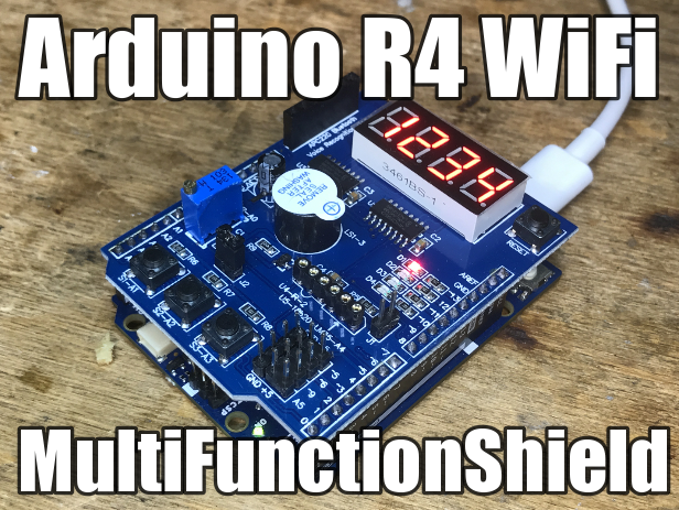
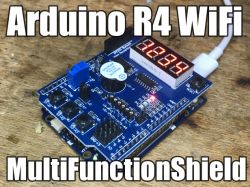
Image of Arduino R4 WiFi with MultiFunctionShield displaying the digits 0234 on a 7-segment display.
Today I will present the process of porting a library supporting MultiFunctionShield to Arduino R4 and briefly demonstrate its capabilities, i.e. displaying data on a 7-segment, 4-digit display and controlling the keyboard and buzzer. By the way, we will also see how you can implement a timer with an interrupt on R4 using fspTimer.h . This is enough to run this shield with the new Arduino.

MultiFunctionShield
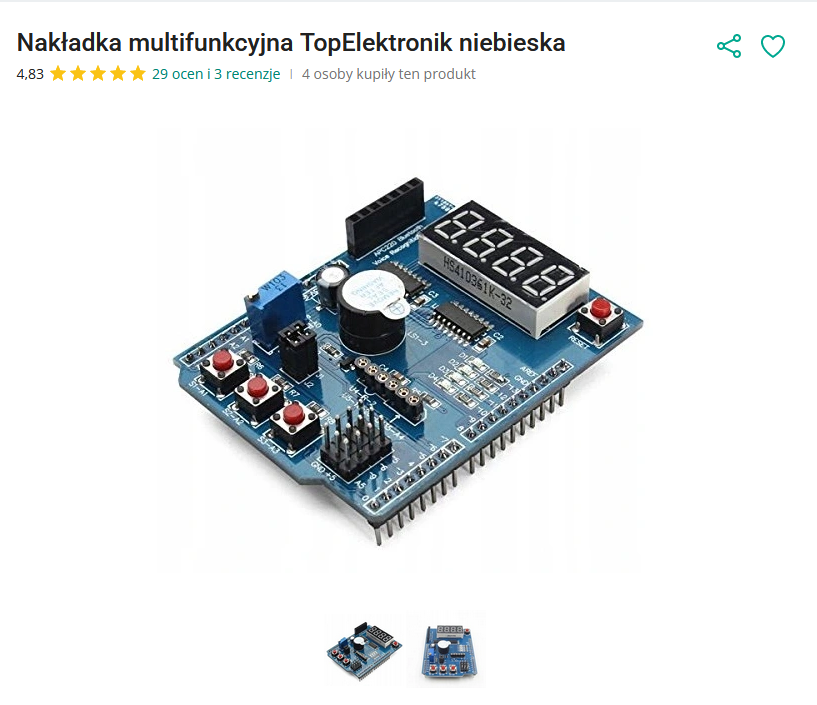
The "multifunctional" shield is one of the cheapest Arduino accessories I know - you can buy it for less than PLN 10 on our Polish shipping portal:
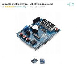
TopElektronik multifunction shield for Arduino, visible display and components
The graphic comes from Github .
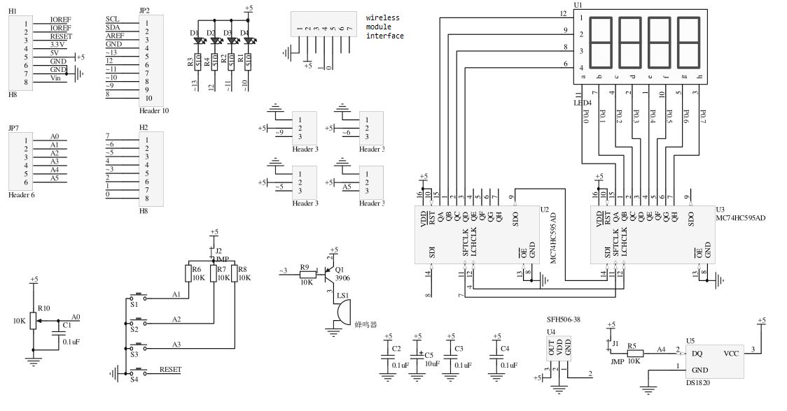
Diagram:
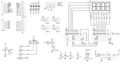
Electrical schematic of MultiFunctionShield for Arduino
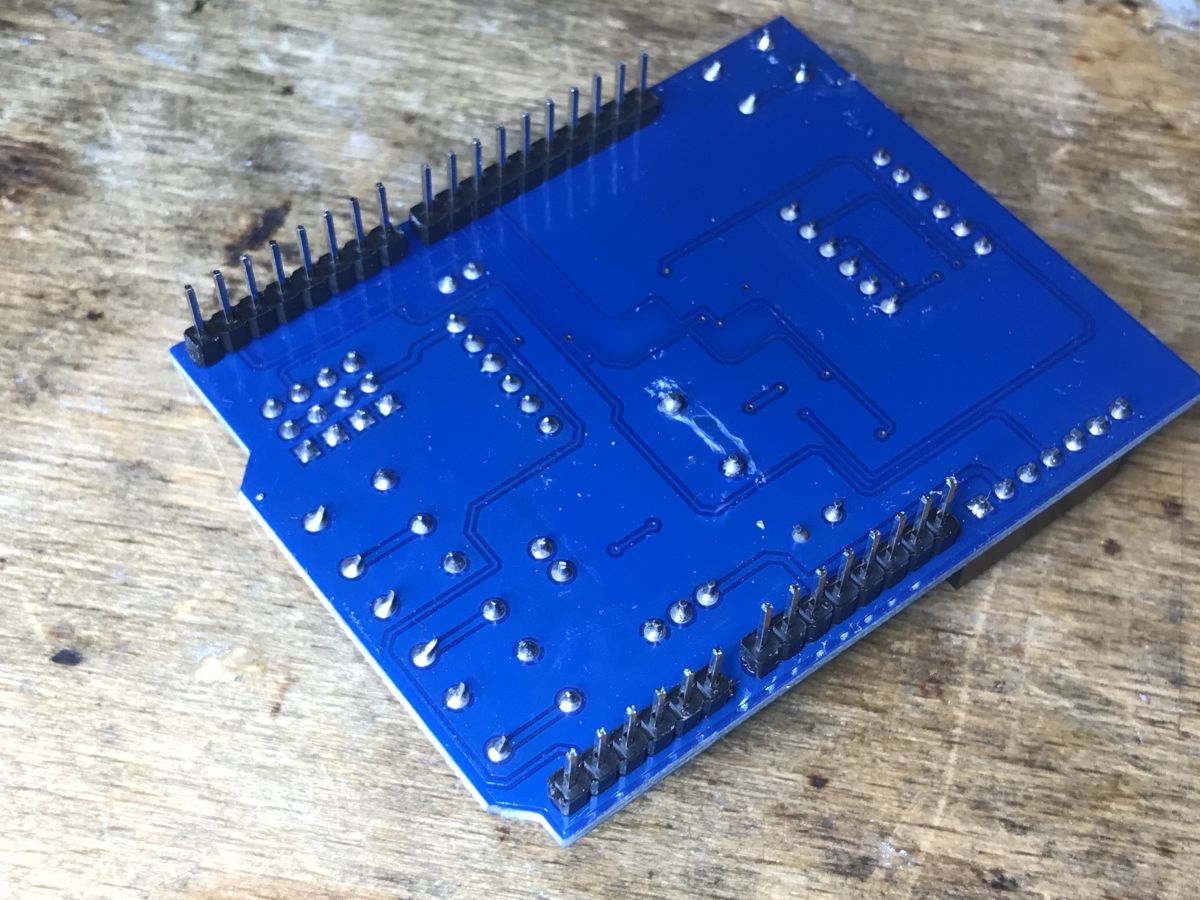
Actual look, some pics from me:
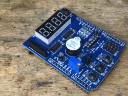
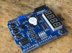
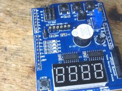
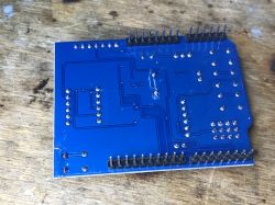
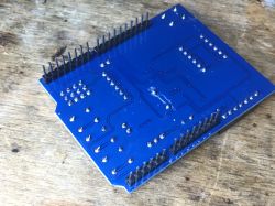
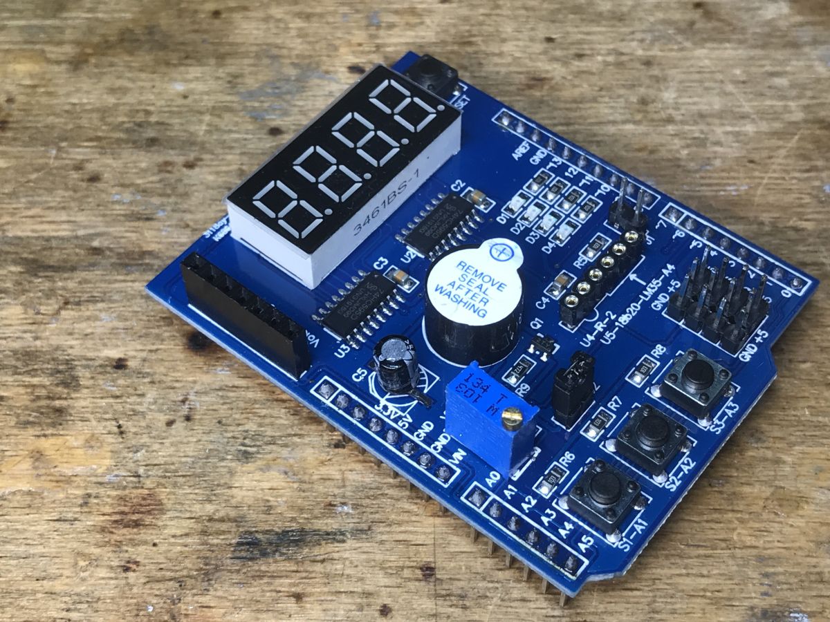
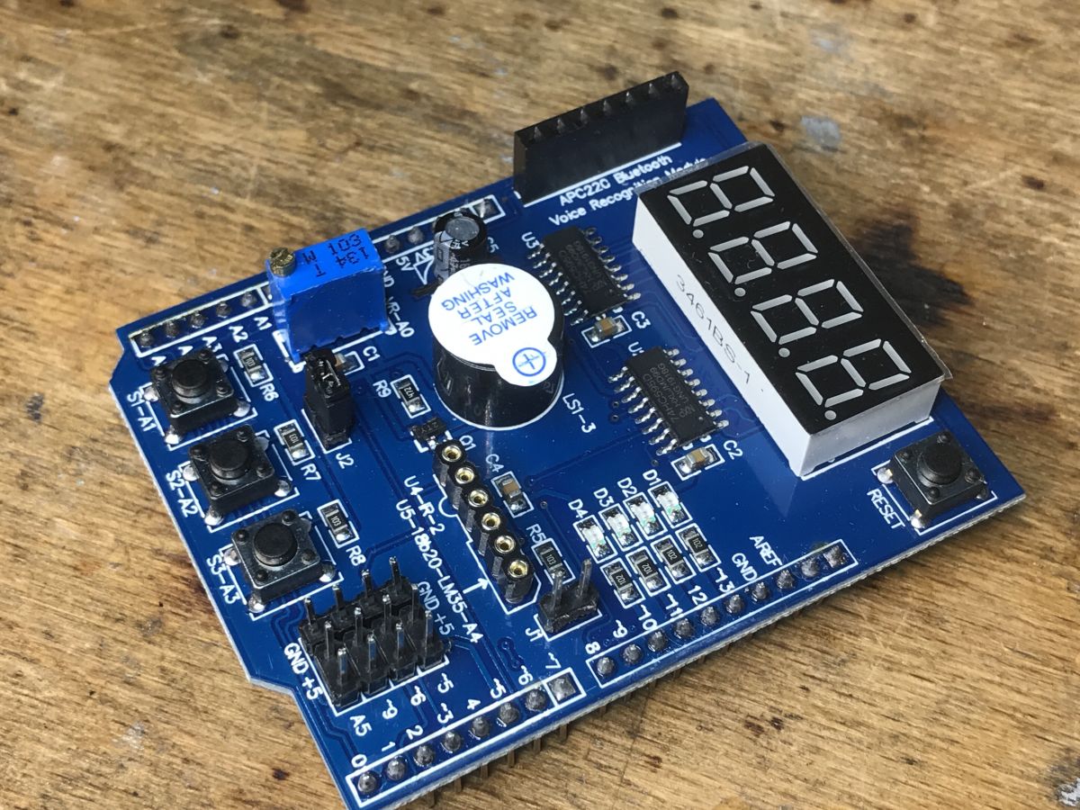
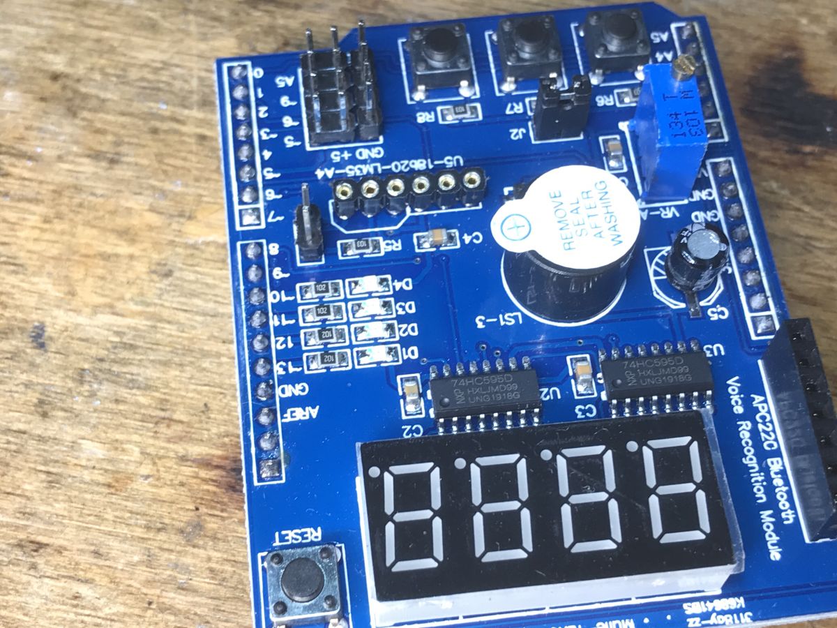
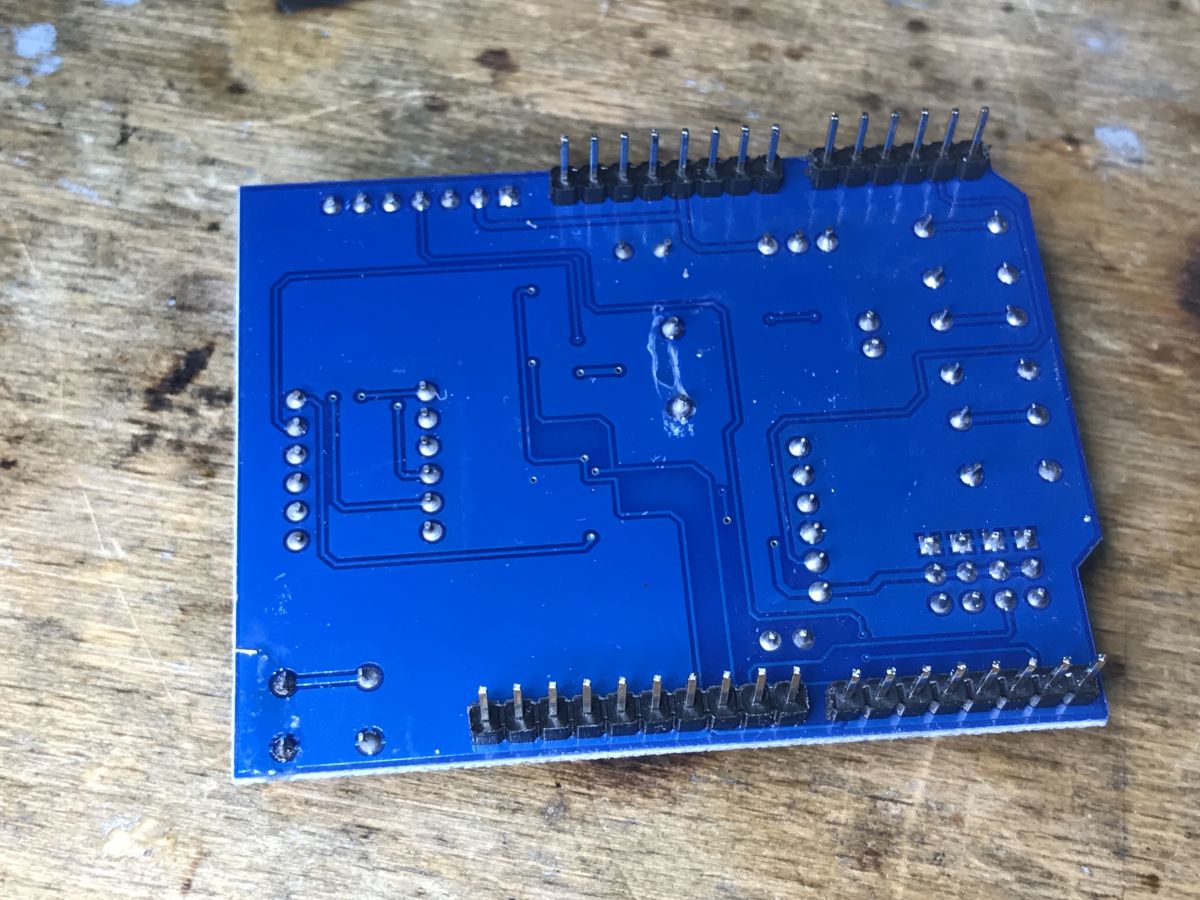
MultiFunctionShield add-on for Arduino with a 7-segment display Multi-function shield for Arduino with 7-segment display MultiFunctionShield board with a four-digit display, buttons, and a buzzer on a wooden table. PCB with visible traces and pins. MultiFunctionShield PCB from the soldering side
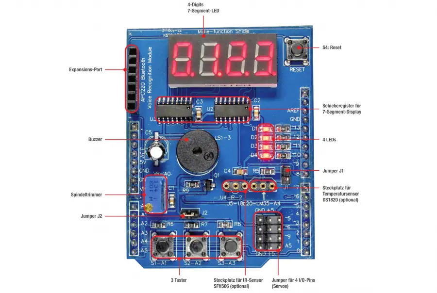
So you might wonder what it offers - basically not much:
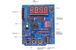
Image of the MultiFunctionShield for Arduino with labeled components.
We have here:
- 7-segment display with 4 digits, controlled by two 74HC595D shift registers connected in cascade (so 3 GPIOs are needed for control)
- three buttons
- buzzer
- several LEDs
- potentiometer
- derived RESET button
- additional slots for various peripherals, IR receiver, DS18B20 temperature sensor, some other extensions
Some basic projects can be done on it. That's what we're going to try to do right now.

Attention! If you don't know how a shift register works or how a 7-segment display works, I recommend you to read other materials on this topic from our forum. Among other things, you can visit my old topic where I was running a similar display on an Arduino Uno R3:
Tuner 7 segment display, starting from Arduino, shift register
There I also discussed shiftOut, which is also used here.


Installing Multi Function Shield
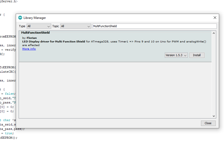
On Arduino Uno R3, the one based on Atmeda, the whole process is very simple. Just install the library with the same name as shield, it is available in Library Manager:
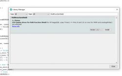
Screenshot of Arduino library management for MultiFunctionShield.
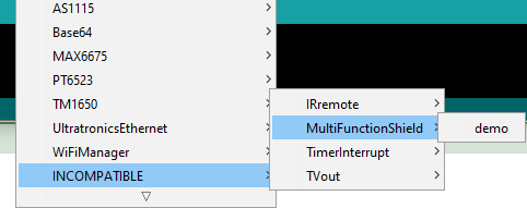
Unfortunately, it is not supported on R4. Even the Arduino IDE hides it specifically from us, because in the library settings (library.properties) is marked to work only on AVR:
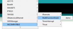
Screenshot of the Arduino IDE interface showing library selection options, with MultiFunctionShield highlighted.
Even if we force it open, it won't compile.

Compilation warning during an Arduino project regarding libraries.
We'll need to port it to a new platform, but let's get to the code first.
This library is available on Github at:
https://github.com/coderfls/Arduino_MultiFunctionShield
In this topic, I will quote the code of this library, it is in accordance with its license - CC0

Overview of the MultiFunctionShield library
The downloaded libraries reside in the Arduino folder, for me it is:

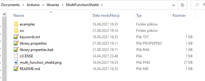
C:\Users\Admin\Documents\Arduino\libraries\MultiFunctionShield\src

We have there e.g. library.properties file:
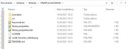
Screenshot showing the contents of the MultiFunctionShield library folder.
Let's see its contents:

name=MultiFunctionShield
version=1.5.3
author=Florian
maintainer=Florian
sentence=LED Display driver for Multi Function Shield 
paragraph=for ATmega328, uses Timer1 => Pins 9 and 10 on Uno for PWM and analogWrite() are effected
category=Display
url=https://github.com/coderfls/Arduino_MultiFunctionShield
architectures=avr
includes=avr/interrupt.h

You will need to modify the architectures entry. Now let's go through the folders. There is only an example sketch in examples:
Code: C / C++
Log in, to see the code

Pretty much everything in the code above should be self explanatory, but I'll cover it anyway:
Code: C / C++
Log in, to see the code

In the above code, an object of the MultiFunctionShield class is created and its display multiplexing is started.
Code: C / C++
Log in, to see the code

The above snippet just displays the given number on the shield's display.
It is worth remembering that the display multiplexing is constantly running in the background, because it has to refresh the display manually.
The rest of the demo of this shield should be clear, because these are ordinary operations on the Arduino GPIO, including the buzzer control.

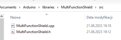
Ok, back to the porting issue. Let's check the source code of this library first:
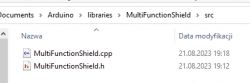
Screenshot of folder with MultiFunctionShield.cpp and MultiFunctionShield.h files
MultiFunctionShield class header:
Code: C / C++
Log in, to see the code

The AVR interrupt header is already included here. It will need to be removed. There are also pins defined here (rigidly, because it is for this particular shield, so when we look for what is connected where, we have a cheat sheet here), and there is a class declaration ...

MultiFunctionShield class implementation:
Code: C / C++
Log in, to see the code

Here you can see that the AVR timer was used for multiplexing. It is set in this snippet:
[syntax=c]
TCCR1A = 0; // Register loeschen
OCR1A = 1000; // Vergleichswert x = (CPU / (2 x Teiler x f)) - 1
TCCR1B |= (1


About Author
p.kaczmarek2
p.kaczmarek2 wrote 14699 posts with rating 12743 , helped 656 times. Been with us since 2014 year.

Comments

FAQ

TL;DR: For Arduino R4 WiFi users, this port keeps a 4-digit shield working by replacing AVR Timer1 code with an R4 timer interrupt; as the author says, "This is enough to run this shield with the new Arduino." It solves the main R4 problem: the original library is AVR-only and hidden in Arduino IDE. [#20702833]

Why it matters: This FAQ shows how to keep a very cheap Multi Function Shield usable on Arduino R4 WiFi without changing its display, buttons, buzzer, or basic wiring.

Area Arduino Uno R3 Arduino R4 WiFi
Library visibility in IDE Available in Library Manager Hidden for this board
Declared architecture avr Not included
Timer approach in library AVR Timer1 + ISR(TIMER1_COMPA_vect) Must use an R4 timer interrupt via fspTimer.h
Build status with original code Intended to compile Does not compile

Key insight: The display logic, pin map, and shiftOut flow mostly stay the same. The real porting work is replacing AVR-only architecture checks and timer interrupt code with an Arduino R4-compatible timer path.

Quick Facts

  • The shield is described as one of the cheapest Arduino accessories, at less than PLN 10, which makes it practical for low-cost demos and training builds. [#20702833]
  • The 4-digit 7-segment display uses two 74HC595D shift registers in cascade, so control needs only 3 GPIOs: latch, clock, and data. [#20702833]
  • Fixed pin assignments in the library include BUZZER_PIN=3, LATCH_PIN=4, CLK_PIN=7, DATA_PIN=8, and LEDs on pins 10, 11, 12, and 13. [#20702833]
  • The example sketch shows display updates and buzzer timing with 2,000 ms delays between numbers, plus buzzer pulses of 50 ms low and 10 ms high. [#20702833]

How do I port the MultiFunctionShield library from Arduino Uno R3 to Arduino R4 WiFi using fspTimer?

Port it by removing the AVR lock-in and replacing the Timer1 interrupt with an Arduino R4 timer interrupt from fspTimer.h. 1. Change library.properties so the library is no longer limited to avr. 2. Remove the ATmega328-only check and avr/interrupt.h. 3. Keep the display and pin logic, but replace ISR(TIMER1_COMPA_vect) and Timer1 register setup with an R4 timer callback that refreshes the 4 display digits. [#20702833]

Why does the original MultiFunctionShield library not appear in Arduino IDE for the Arduino R4 WiFi?

It does not appear because the library declares architectures=avr, and Arduino IDE hides it for non-AVR boards like Arduino R4 WiFi. The thread states that the IDE specifically hides it from R4 users, and even forcing it open still fails to compile because the code targets ATmega328 hardware. [#20702833]

What changes in library.properties are needed to make the MultiFunctionShield library build on Arduino R4?

You need to change the architectures entry so it is not limited to avr. The thread shows architectures=avr and includes=avr/interrupt.h, which matches an AVR-only library. That setting blocks normal use on Arduino R4 WiFi, so the first edit is to remove the AVR-only architecture restriction. [#20702833]

Which parts of the MultiFunctionShield source code are AVR-specific and need to be replaced for Arduino R4 compatibility?

The AVR-specific parts are the ATmega328-only preprocessor check, the avr/interrupt.h include, the Timer1 register setup, and the AVR ISR declaration. The code uses #ifndef __AVR_ATmega328P__, includes the AVR interrupt header, writes Timer1 registers such as TCCR1A, TCCR1B, and OCR1A, and ends with ISR(TIMER1_COMPA_vect). Those parts must be replaced for R4 compatibility. [#20702833]

How is Timer1 used in the original MultiFunctionShield library to multiplex the 4-digit 7-segment display?

Timer1 drives periodic refresh of the display in the background. In begin(), the library clears Timer1 registers, sets OCR1A = 1000, enables compare-match interrupt logic, and calls ISRFunc() from ISR(TIMER1_COMPA_vect). ISRFunc() advances through digits 0 to 3, so one digit lights at a time, fast enough to appear continuous on the 4-digit display. [#20702833]

What is fspTimer.h in Arduino R4, and how is it used to create timer interrupts?

fspTimer.h is an Arduino R4 timer interface that the thread uses to implement an interrupt-based timer on the new board. "FspTimer is a timer interface that creates periodic callbacks on Arduino R4, replacing direct AVR register control." In this port, it serves the same role as Timer1 on Uno R3: it repeatedly refreshes the multiplexed display so the shield works on R4. [#20702833]

What is display multiplexing, and why does the MultiFunctionShield library need it for the 7-segment display?

Display multiplexing means the library lights one digit at a time and cycles through all 4 digits very quickly. "Display multiplexing is a display-control method that refreshes several digits sequentially, reducing pin usage while relying on repeated updates to look steady." The shield needs it because the display is not self-refreshing; the library must keep updating it in the background through interrupts. [#20702833]

How does the Multi Function Shield connect its 4-digit 7-segment display through two 74HC595D shift registers?

The shield connects the 4-digit display through two cascaded 74HC595D shift registers, controlled with 3 lines. The library calls shiftOut(DATA_PIN, CLK_PIN, MSBFIRST, ...) twice: first for segment data, then for digit selection. After that, it toggles LATCH_PIN to transfer both bytes to the outputs and light the chosen digit. [#20702833]

What pins are assigned to the buzzer, buttons, LEDs, potentiometer, and shift register control lines on the Multi Function Shield?

The library hard-codes the shield pin map. LEDs use pins 13, 12, 11, and 10. The buzzer uses pin 3. Buttons use A1, A2, and A3. The potentiometer uses A0, and the optional LM35 pin is A4. The shift-register control lines are LATCH_PIN=4, CLK_PIN=7, and DATA_PIN=8. [#20702833]

Why does the MultiFunctionShield library include avr/interrupt.h and an ATmega328-only check, and what should replace them on Arduino R4?

It includes them because the original library was written only for Arduino Uno, Nano, and similar ATmega328 boards. The header file explicitly throws an error outside __AVR_ATmega328P__, and it includes avr/interrupt.h for the Timer1 ISR. On Arduino R4, those AVR-specific parts should be replaced with an R4-compatible timer interrupt path using fspTimer.h. [#20702833]

Arduino Uno R3 vs Arduino R4 WiFi for Multi Function Shield projects: what differences matter when porting libraries?

The key difference is not the shield wiring but the software platform. On Uno R3, the library installs normally and uses AVR Timer1 registers directly. On Arduino R4 WiFi, the IDE hides the library because it is marked avr, and the AVR-only code does not compile. Porting therefore focuses on architecture checks and interrupt handling, not on the shield’s 3-wire display interface. [#20702833]

How can I display positive and negative numbers on the Multi Function Shield's 4-digit 7-segment display?

Use MFS.Display(value) with a signed integer. For positive values, the library fills digits from the right and blanks unused positions. For negative values, it places a minus sign on the left using SEGMENT_MINUS = 0xBF, then shows the absolute value on the remaining digits. The example and source both show support for values like 1234 and -56. [#20702833]

What causes the buzzer to make a short unwanted sound at startup on the Multi Function Shield, and how do I prevent it?

The unwanted chirp happens if the buzzer pin is not driven high before configuring it as an output. The library avoids that by calling digitalWrite(BUZZER_PIN, HIGH); first, then pinMode(BUZZER_PIN, OUTPUT);. The author comments this directly: the order matters, or you get a short sound at startup. [#20702833]

How do shiftOut and the 74HC595 work together to drive a 7-segment display on an Arduino shield?

shiftOut sends serial bit patterns into the cascaded 74HC595 registers, and the latch pin updates the outputs together. One shifted byte defines which segments should light, and the second byte selects which of the 4 digits is active. This method cuts display control to 3 GPIOs while still driving multiple segments and digit lines. [#20702833]

What practical projects can I build with the cheap Multi Function Shield using its display, buttons, buzzer, LEDs, and potentiometer?

You can build simple interactive demos, counters, status displays, button-driven menus, alarms, and basic training projects. The thread lists a 4-digit display, 3 buttons, a buzzer, several LEDs, a potentiometer, a reset button, and expansion points for parts like an IR receiver or DS18B20 sensor. That combination is enough for compact learning projects on both Uno R3 and a ported R4 setup. [#20702833]
Summary generated by AI based on the discussion content.
%}