Acoustic amplifier for those who hear differently
Similar topics have already been discussed on the Forum, but my device is the most mine, so I decided to share a report of its construction with those who either have hearing problems or would like to make a similar device for someone with such a problem.
I'm not an acoustician and I don't do acoustics at work, so professionals versed in the art may find the presented device technically poor, incompatible with the art and Be at all, but it has an undeniable utility value confirmed by the person concerned, with whom I can now communicate freely.
I know you can buy a fairly decent amplifier on the MAX9814, however, where is the fun and learning here?
So I borrowed the base schematic from the website : Link .
I made this device unchanged, but it had some significant drawbacks such as a very high resting current ( battery life ) and a lot of noise.
So I decided to simulate this circuit under LTSpice, which pointed me in the direction of improvements.
This resulted in a circuit with relatively low noise, a flat gain characteristic from about 80Hz to the limits of audibility ( probably around 10kHz ) and a negligible resting current of less than 3mA.
The final shape of the circuit is shown in the diagram below:
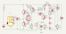 .
.
and here is a revised version of the final layout form:
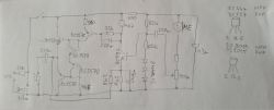 .
.
What the layout is like everyone can see. A board was also created, of course :
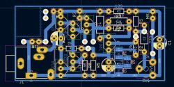 .
.
and then it was enhanced with the relevant electronic components:
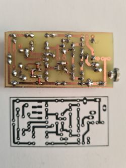
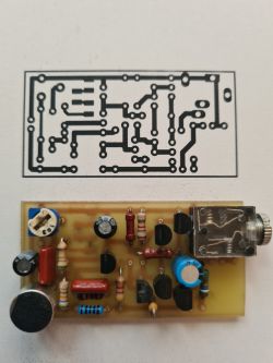
It's not a master craftsmanship, but it works and follows the schematic.
After attaching the LiIon battery, headphones and switch, I performed tests and basic measurements.
Actually the resting current is about 3.2mA and the noise is very negligible. The circuit picks up sounds well from about 5 metres and, most importantly, does not distort them in the audible range of sound waves. The goal has therefore been achieved.
Now only the casing remained to be made. Since I acquired a 3D printer, this is no longer a problem and instead of adapting the device to the housing I have, I make a housing for the circuit I made. Very convenient and quick, and I don't have to search for the right box.
The box consists of the bottom and of course the top :
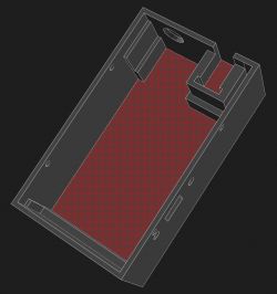
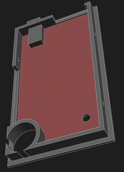 .
.
And after printing it looks like this:
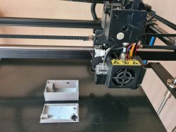 .
.
Now the previously made layout goes into a new box :
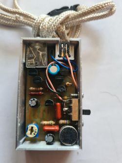
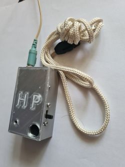
and that's pretty much it.
One more thing, I originally used a BC109C transistor in the input stage, but the noise was too high, so I replaced it with a 2SC9014. The noise dropped well below the expected value, so that's how it stayed.
I use an old power supply from a Nokia phone as a charger. The battery is charged with about 100mA through a 20 ohm resistor. Ten hours is completely sufficient to fully charge the battery. This is not the recommended way to charge LiIon batteries, but if someone wants to, they can connect an external circuit purchased from MyFriends instead of a simple phone charger..
I use 32 ohm headphones connected in series on the output, but both 16 and 64 will work well too. Volume control is via a potentiometer on the headphone cable.
I don't expect applause, but if this device is useful to someone, I think I'll consider the goal achieved.
I encourage esteemed colleagues to enrich the topic with their valuable comments and ideas.
I'm not an acoustician and I don't do acoustics at work, so professionals versed in the art may find the presented device technically poor, incompatible with the art and Be at all, but it has an undeniable utility value confirmed by the person concerned, with whom I can now communicate freely.
I know you can buy a fairly decent amplifier on the MAX9814, however, where is the fun and learning here?
So I borrowed the base schematic from the website : Link .
I made this device unchanged, but it had some significant drawbacks such as a very high resting current ( battery life ) and a lot of noise.
So I decided to simulate this circuit under LTSpice, which pointed me in the direction of improvements.
This resulted in a circuit with relatively low noise, a flat gain characteristic from about 80Hz to the limits of audibility ( probably around 10kHz ) and a negligible resting current of less than 3mA.
The final shape of the circuit is shown in the diagram below:
 .
.
and here is a revised version of the final layout form:
 .
.
What the layout is like everyone can see. A board was also created, of course :
 .
.
and then it was enhanced with the relevant electronic components:


It's not a master craftsmanship, but it works and follows the schematic.
After attaching the LiIon battery, headphones and switch, I performed tests and basic measurements.
Actually the resting current is about 3.2mA and the noise is very negligible. The circuit picks up sounds well from about 5 metres and, most importantly, does not distort them in the audible range of sound waves. The goal has therefore been achieved.
Now only the casing remained to be made. Since I acquired a 3D printer, this is no longer a problem and instead of adapting the device to the housing I have, I make a housing for the circuit I made. Very convenient and quick, and I don't have to search for the right box.
The box consists of the bottom and of course the top :

 .
.
And after printing it looks like this:
 .
.
Now the previously made layout goes into a new box :


and that's pretty much it.
One more thing, I originally used a BC109C transistor in the input stage, but the noise was too high, so I replaced it with a 2SC9014. The noise dropped well below the expected value, so that's how it stayed.
I use an old power supply from a Nokia phone as a charger. The battery is charged with about 100mA through a 20 ohm resistor. Ten hours is completely sufficient to fully charge the battery. This is not the recommended way to charge LiIon batteries, but if someone wants to, they can connect an external circuit purchased from MyFriends instead of a simple phone charger..
I use 32 ohm headphones connected in series on the output, but both 16 and 64 will work well too. Volume control is via a potentiometer on the headphone cable.
I don't expect applause, but if this device is useful to someone, I think I'll consider the goal achieved.
I encourage esteemed colleagues to enrich the topic with their valuable comments and ideas.


Comments
I suggest doing a little test to show that the mere fact that the 'interested person' hears better or hears at all is already something, but something will be missing. Just hide from the 'interested person'... [Read more]
Thanks, I for one am glad to see hearing aid designs still appearing. It reminds me of the beautiful days of electrode from the early days of the service. Respect to you and for presenting the construction. Write... [Read more]
"Helpful post" clicked. The type of circuit breaker used by the Fellow has the drawback of a rather flimsy slider design. I suggest replacing the switch currently used with one from the photo below. This... [Read more]
Very interesting analogue design, hearing aids used to be made like this at Omig, on germanium transistors: http://bee.mif.pg.gda.pl/Oktoda/index.php/AS-571 https://a.allegroimg.com/s1024/0c44b3/18d71e9a4772b0b8b948573a334b In... [Read more]
You are right in the general case, and undoubtedly anyone wishing to make such a device on their own should take your advice into account for the benefit of the user of such a device. However, in this... [Read more]
I checked out of curiosity and there is a free 'hearing test' app anyone can easily assess the state of their hearing organ. [Read more]
Why transistors Q5 and Q6 and not ordinary diodes in this location? Does this have any significant effect or influence on anything (on e.g. noise)? [Read more]
In the first version I used 1N4148 diodes, which is what was recommended, but I noticed on the oscilloscope a waveform skip ( actually it was a saddle) when switching the output transistors. After replacing... [Read more]
. Yes, this is crossover distortion. It's just that when you used diodes there was too little resting current for the terminal transistors. Apparently transistors Q5 and Q6 as diodes have a minimally... [Read more]
Thanks for the expert explanation and definition. "Cross-cutting" - nice word :) . I did not pair transistors Q5 and Q6 but Q3 with Q5 and Q4 with Q6 to match the voltage drops across the connectors... [Read more]
This is also unnecessary because all that matters is the sum of the voltage drops on Q5 and Q6. And in what proportions and whether they correspond exactly to the E-B voltage drops of transistors Q3 and... [Read more]
Have you not thought about the TDA2822M? It will replace 5 transistors. [Read more]
. It draws about 5mA of resting current at 3.7V supply. More than the author managed to wring out in this title project. And this, as I understand it, was also one of the design goals, i.e. to reduce... [Read more]
I considered various configurations and circuits, both integrated and less integrated. In the end, the spirit of the experimenter and a foolish belief in my abilities in a field in which I had no experience... [Read more]
The TDA2822 does not do resting current problems. Classical class AB power stages have current regulation and a transistor to maintain the correct voltage between the bases of the power transistors. I... [Read more]
If not a 2822/7050 then perhaps a ne5532 opamp plus a complementary AB power amplifier would suffice, all covered by the feedback. Minimal components, low noise and low resting current. [Read more]
I have noticed that there have been proposals for designs based on a variety of integrated circuits, but the proposals are so far very general. My problem - and I think a lot of people have a similar... [Read more]
The idea is more or less as shown in the diagram https://obrazki.elektroda.pl/6165262800_1719329224_thumb.jpg . [Read more]
The amplifier schematic looks logical and is uncomplicated, however, have you tested it? Furthermore, it seems to me by the output transistors that these headphones can have even a few watts of power,... [Read more]