Disassembling and Flashing Tuya BSD29 UK Smart Plug + DS18B20 Sensor Mod [WL2S] [LN882H] [BL0937]
Here is a look inside a generic 20A Tuya BSD29 UK smart plug with energy metering capabilities. I will unsolder the main PCB, the module and then flash it to run OpenBeken, cutting it off from all Tuya cloud services. I'll also add a DS18B20 temperature sensor so the temperature inside the casing can be measured.
This black BSD29 was purchased from the Cerhot Smart Store on Ali Express https://www.aliexpress.com/item/1005006573066580.html

Like many plugs, this was welded/glued together very well, meaning some brute force and pressure is required to open. In my vice I clamped the device several millimetres just below the circular rim of the bottom of the plug. This should allow the vice to squash the side wall of the case in very slightly, opening up some small gaps along the glue gap.
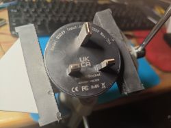
I did not film this process (next time!), but the vice was pretty tight. As small gaps opened I used a scalpel to dig down into those gaps, the glue audibly cracking apart as this is done. Rotated the unit around repeatedly until it was more broken apart than not. Be prepared to give it some force. Be careful crushing the button in.
Once inside we can see its guts, including a Lightning Semiconductor LN882H based WL2S module.
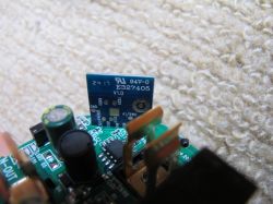
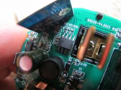
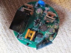
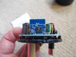
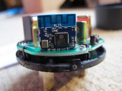
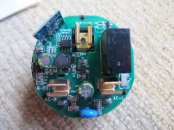
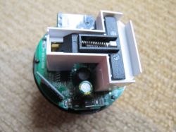
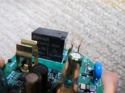
And to reach the bottom of the module the live and neutral pins need to be desoldered. This can be achieved with plenty of flux, solder braid and some patience. Heating and lifting each side of the PCB fractionally, in turn, until the legs are freed.
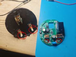
Then the same with flux and braid to remove the WL2S. After which the module can be soldered ready for power and UART flash/backup.
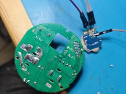
(Those convenient GND and 3.3V test pads have given me an idea.)
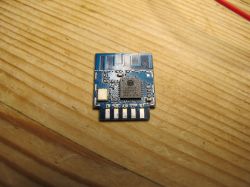
I have not been able to obtain a datasheet for the WL2S yet. It is not a Tuya module. I made this to add missing detail for me and others in the future:
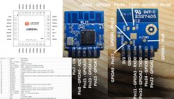
And with connections soldered as follows
WL2S TXD1 -> USB-TTL RX
WL2S 3V3 -> 3.3V external PSU
WL2S GND - > PSU GND/USB-TTL GND
we get the following boot log captured at 921600 baud
switching to TXD0/RXD0 to the USB-TTL adaptor and grounding A9 we put the LN882H into UART download mode when powered. Which means the attached zipped Python script and exe file can be run to download the 2mb factory firmware to a file. This process takes about 40 minutes.
As detailed in this thread I flashed OpenLN to the module using the separate GUI program.
I have a bag of 10 Dallas/Maxim fake DS18B20 sensors and those nicely placed 3v3 and ground pads seemed like they could be put to good use. There are also the unused GPIOs A1 and A5 on the back of the module.
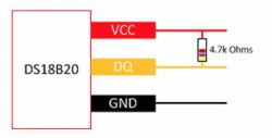
With a 4.7k resistor between the data and VCC legs I tested the sensor working on GPIOA1 on an LN882H test device.
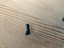
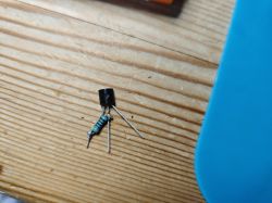
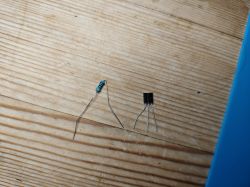
With some heatshrink protection, hot glue gun blobs and some careful routing of some wires, the sensor seems to sit fairly happily in this gap in the plug
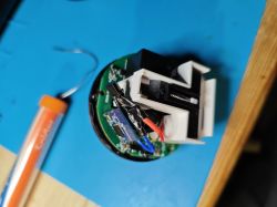
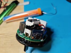
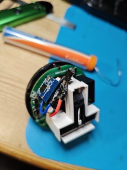
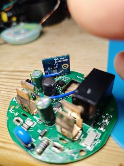
At this point I've soldered the WL2S back into the PCB and tested OpenBeken boots and broadcasts an access point as expected. As luck would have it, the BSD34 template is identical for this device, so that was easy. With the DS18B20 this means:
which looks like
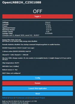
But for the basic BSD29 OBK template is:
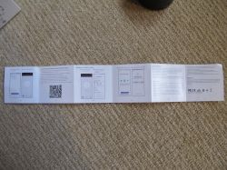
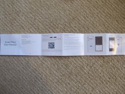
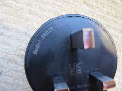
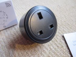
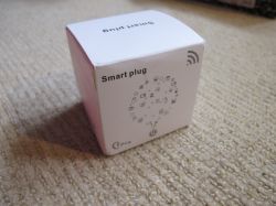
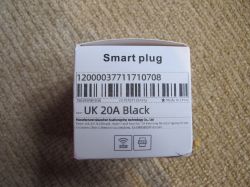
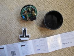
And finally, some more pics of the packaging, manual and device
https://github.com/OpenBekenIOT/webapp/pull/158
This black BSD29 was purchased from the Cerhot Smart Store on Ali Express https://www.aliexpress.com/item/1005006573066580.html

Like many plugs, this was welded/glued together very well, meaning some brute force and pressure is required to open. In my vice I clamped the device several millimetres just below the circular rim of the bottom of the plug. This should allow the vice to squash the side wall of the case in very slightly, opening up some small gaps along the glue gap.

I did not film this process (next time!), but the vice was pretty tight. As small gaps opened I used a scalpel to dig down into those gaps, the glue audibly cracking apart as this is done. Rotated the unit around repeatedly until it was more broken apart than not. Be prepared to give it some force. Be careful crushing the button in.
Once inside we can see its guts, including a Lightning Semiconductor LN882H based WL2S module.


And to reach the bottom of the module the live and neutral pins need to be desoldered. This can be achieved with plenty of flux, solder braid and some patience. Heating and lifting each side of the PCB fractionally, in turn, until the legs are freed.

Then the same with flux and braid to remove the WL2S. After which the module can be soldered ready for power and UART flash/backup.

(Those convenient GND and 3.3V test pads have given me an idea.)
I have not been able to obtain a datasheet for the WL2S yet. It is not a Tuya module. I made this to add missing detail for me and others in the future:

And with connections soldered as follows
WL2S TXD1 -> USB-TTL RX
WL2S 3V3 -> 3.3V external PSU
WL2S GND - > PSU GND/USB-TTL GND
we get the following boot log captured at 921600 baud
Code: Text
switching to TXD0/RXD0 to the USB-TTL adaptor and grounding A9 we put the LN882H into UART download mode when powered. Which means the attached zipped Python script and exe file can be run to download the 2mb factory firmware to a file. This process takes about 40 minutes.
Code: Text
As detailed in this thread I flashed OpenLN to the module using the separate GUI program.
I have a bag of 10 Dallas/Maxim fake DS18B20 sensors and those nicely placed 3v3 and ground pads seemed like they could be put to good use. There are also the unused GPIOs A1 and A5 on the back of the module.
With a 4.7k resistor between the data and VCC legs I tested the sensor working on GPIOA1 on an LN882H test device.


With some heatshrink protection, hot glue gun blobs and some careful routing of some wires, the sensor seems to sit fairly happily in this gap in the plug


At this point I've soldered the WL2S back into the PCB and tested OpenBeken boots and broadcasts an access point as expected. As luck would have it, the BSD34 template is identical for this device, so that was easy. With the DS18B20 this means:
Code: JSON
which looks like

But for the basic BSD29 OBK template is:
Code: JSON
And finally, some more pics of the packaging, manual and device


https://github.com/OpenBekenIOT/webapp/pull/158


Comments
Very nice mod, but aren't the internals of the plug heating up the sensor? Maybe it would make sense to let the DS18B20's head peak out a little bit out of the device case. Still, take care, it seems the... [Read more]
yes, but I was only after an idea of the temps inside rather than the environment outside. But mostly so I have a DS18B10 always paired with LN882H ready for immediate testing. [Read more]
in the unlikely event anyone swaps the WL2S for a WB2S, the pin assignments would then be the following for this device "6": "LED_n;1", "7": "BL0937CF;0", "8": "BL0937CF1;0", "10":... [Read more]