logo elektroda
logo elektroda
X
logo elektroda
ADVERTISEMENT
Treść została przetłumaczona polish » english Zobacz oryginalną wersję tematu
  • #121 7954387
    Matt_x89
    Level 12  
    After applying the 5V voltage to 8, the motor driver's foot starts without any problems. I checked all the legs you asked for and there is tension on them. The motor controller stand is well soldered.
  • ADVERTISEMENT
  • #122 7954415
    mlassota
    Level 18  
    Matt_x89 wrote:
    After applying the 5V voltage to 8 the motor driver's foot starts without any problems. I checked all the legs you asked for and there is tension on them. The motor controller base is well soldered.
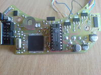
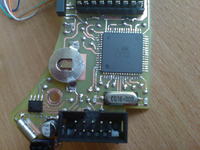
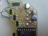
    There remains the question of soldering the IDC10 socket - for programming - is it soldered on both sides of the PCB?

    If so, the problem lies in the processor ... After switching on the voltage on the leg 51 should be 5V immediately - no pilot signal is needed ...
  • #123 7954447
    Matt_x89
    Level 12  
    The IDC10 socket is well soldered. I will check all the guides tomorrow.
  • #124 7955173
    Matt_x89
    Level 12  
    Hello.
    I checked the signals on all the legs and this is what I received:
    (7) RCINT 4.89V (at a signal from the pilot 4.07V)
    (9) INT7 0.11V (with approx. 4,89V reflecting surface)
    (11) SCK 0.02V
    (15) RED 0.02V
    (16) GREEN 0.02V
    (17) BLUE 0.02V
    (20) RESET 5.09V
    (21) VCC 5,11V
    (22) GND approx
    (25) SCL 5.09V
    (26) SDA 5.09V
    (27) RDX 5.09V
    (28) TDX 4.70V
    (32) SQW 0.05V
    (51) MOTOR 0,02V
    (52) VCC 5,11V
    (53) GND approx
    (63) GND approx
    (64) VCC 5,11V

    I checked the connections between the IDC10 socket and the processor and everything is OK.
    on the quartz legs I observed the voltage of 0.07 on the MILI scale because in volts there was no reaction which I saw on the quartz of the DS1307 chip. Should it be like that?

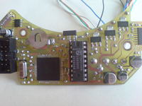
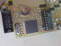
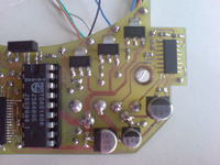
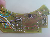
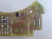
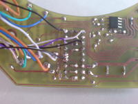
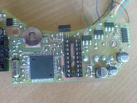
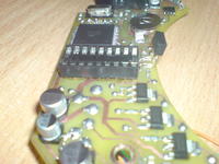
    Here are the pictures of the layout.

    HDDClock - clock from hard drive HDDClock - clock from hard drive HDDClock - clock from hard drive HDDClock - clock from hard drive HDDClock - clock from hard drive
    HDDClock - clock from hard drive HDDClock - clock from hard drive HDDClock - clock from hard drive HDDClock - clock from hard drive
  • #125 7955259
    mlassota
    Level 18  
    Hello Colleague

    I look at the tiles and intrigue me as you soldered from the TOP side - top stand under TDA because you have a simple stand and it can not be soldered on both sides of the plate and this is ABSOLUTELY necessary
    Take a photo of the side of the TDA stand and the IDC10 socket housing raised - it must be in February.
    greetings
    M
  • #126 7955316
    Matt_x89
    Level 12  
    Yes, I agree that you can not solder and I knew it immediately. I decided to circumvent this problem in such a way that before soldering the socket for the scalak I made guides from several wires in places where it is necessary and checked the meter if the circuit is closed. After that I soldered the stand and checked everything again. Besides yesterday, as you advised I gave the 8 TDA 5V outstretched and the engine moved without a problem. In the picture from above it should be seen that I solder guides under the stand in places where it is necessary.

    HDDClock - clock from hard drive HDDClock - clock from hard drive
  • ADVERTISEMENT
  • #127 7955413
    mlassota
    Level 18  
    My friend
    If you are sure about the correctness of soldering, do so
    Put the primitive program into the processor's memory:

    $regfile = "m128def.dat"
    
    
    $crystal = 16000000
    Config Pina.0 = Output
    Config Pinb.5 = Output
    Config Pinb.6 = Output
    Config Pinb.7 = Output
    porta.0=0
    portb.5=0
    portb.6=0
    portb.7=0
    
    Do
    Set    Portb.5
    Wait 1
    Set Portb.6
    Wait 1
    Set Portb.7
    Wait 1
    Set Porta.0
    Wait 3
    Reset Porta.0
    Wait 1
    Reset Portb.5
    Wait 1
    Reset Portb.6
    Wait 1
    Reset Portb.7
    Loop


    Below compiled hex
    He has to turn on the diodes and turn off the engine and then perform the reverse sequence. Let me know what the effect is.

    To upload Hex, use the ISPPROG program available here
    Remember to configure your programmer.
  • #128 7955527
    Matt_x89
    Level 12  
    Thank you for the testing program.
    After uploading it to the processor, the LEDs are always red. It looks like the processor does not make a loop, it just stays in place, it concludes that the remaining colors do not turn on and the motor does not react. Could it show damaged quartz and lack of synchronization for prock?
    Once again, thank you for the test program :)
  • ADVERTISEMENT
  • #129 7955598
    mlassota
    Level 18  
    Try to change the fusebits on the internal 8Mhz oscillator (bits w / g image)

    HDDClock - clock from hard drive

    Below the same program the same but at 8Mhz ... maybe now it will start :)
  • #130 7955649
    Matt_x89
    Level 12  
    I came up with the idea of checking if everything works, but unfortunately the environment has gone crazy for me to program. Could a friend give me this program first on 16Mhz only in 3 versions, let's say it starts with a green color. The next program would start with the blue color and the last one would start with the engine being switched on.
    If this is not a problem, I would ask for such versions of this program. Then it would be known that the percentages start the system and the wine can be on the quartz side
  • ADVERTISEMENT
  • #131 7955725
    mlassota
    Level 18  
    In the appendix programs starting from different pins - the program name is the name of the port from which the program starts - I hope I did not crash any error in the program :) - in the end is so complicated :)
  • #132 7955769
    Matt_x89
    Level 12  
    Thank you very much for the programs. After uploading b5, the diodes are red, b6 green, b7 blue, and the engine turns only (after about 40 seconds of turning for a while it slows down as if it was turned off and continues to spin). Now the question remains why the loop does not work and the ports are not activated in turn. Is this momentary turning off the motor and the lack of port switching indicates the damaged quartz?
  • #133 7955832
    mlassota
    Level 18  
    Try to really switch the processor to an internal oscillator at 8 mhz and then upload the programs from the file below. Exclude quartz failures.
    Solder out capacitors with quartz - maybe one has a puncture and pulls to the mass

    The upside is that we are sure that the ports are operational and did not burn during the soldering
  • #134 7955949
    Matt_x89
    Level 12  
    I changed the source signal to the internal 8MHz and uploaded the program on this version. Earlier I was soldering the quartz and the system was behaving unchanged. then I switched to external 16Mhz clock and the system refuses to cooperate here:

    HDDClock - clock from hard drive
  • #135 7956030
    mlassota
    Level 18  
    And porcek has connected quartz?
    If not, he has the right to behave like that
  • #136 7956548
    Matt_x89
    Level 12  
    I re-soldered the quartz to the system before I changed the bits and uploaded the program to 8MHz. The system can not be recognized by any program at all.

    Added after 1 [hours] 53 [ minutes]:

     I decided to desolder the slingshot and ordered a new system and quartz. Thank you again for the test programs. I wanted to ask if you guessed what could be the cause of the damage to the prock, or what could I do wrong? Could the temperature of the soldering tip damage the processor?
  • #137 7958155
    mlassota
    Level 18  
    Hello, Kolegów

    I undressed my watch and uploaded the test programs.
    On a properly folded (working) watch they work the most.
    The LEDs light up one by one and the engine starts up ...
    So the problem lies in something else.
    Perhaps you've overheated the chip during soldering and maybe the quartz is guilty, capacitors ...
    I thought that when I was at work and writing test programs, I screwed something up, but I'm sure it does not work on my ass.
    Before desoldering the processor, if you did not do it try to insert a different quartz - new - not even in the smd enclosure - maybe it overheated ... There is also the possibility that the processor fell from ESD ... although I solded a few and did not spoil in this way.
    What are you programming - what programmer? If under LPT, check if the computer is connected to ground.
  • #138 7958261
    Matt_x89
    Level 12  
    I've desoldered the slingshot now. The processor was soldered to a soldering station with a 0.5mm tip and each soldered separately, I was also thinking about inserting a 1mm tip and applying one stop at one stroke.

     I have installed AVR Studio 4 on my computer and loaded the hex file from this program and set fuse. Could the other systems damage the slingshot, walk on the signals that I put in the morning it looks like everything is correct? Which download program do you recommend to install? I would like to avoid damage to the next prock so I'm open to any suggestions ;)
  • #139 7965177
    mb1988
    Level 12  
    I've always uploaded the program using avrdude. I have it configured so that I call it from the Programmers Notepad level from the WinAVR package, it handles it very easily.

    As for your problems with the watch, you wrote that the target program did not start, but with test programs written by a colleague mlassota that's right. When we look into the main.c file of the watch source, we notice that before switching on the engine it first communicates with the RTC system. Therefore, there is a small chance (although anything is possible) that it hangs when you try to make contact with this system. It is easy to check if the RTC system has been correctly initialized - on its seventh leg a rectangular wave with a frequency of 4096Hz should appear.
  • #140 7967045
    utak3r
    Level 25  
    After watching the movie, I was about to write that it would be good to add 12 dots on the edge of the dial and slightly shorter hints for increasing the readability of the clock, but only later I read the principle of operation ... it is rather unfeasible in the solution with the aperture.

    And if you do a typical POV, with a ruler of diodes on the plate ... the problem with the aesthetic performance of such a thing, it would be best to cut the gap and place the ruler in it, or under the plate to make it shine up. With this solution, it would be possible to create a clearer image of the dial.

    Creation of the author's design: for a high five, everything elegant and pleasant, zero chalay. :) The decoration is also very interesting. Could you explain how your friend put the pattern on the surface? Directly on plexiglass she drew, or how?
  • #141 7967511
    mb1988
    Level 12  
    The idea with the led line is worth considering, but it also has its drawbacks - you will not get such a smooth image in this way, it will be divided into concentric circles. But it's a matter of taste.

    The graphics you see were made by hand with a pen on a piece of paper. This card was then cut and placed under 2mm plexiglass.
  • #142 7967543
    mlassota
    Level 18  
    Hello
    Problem 2 - feeding the ruler on a rotating plate ...
    Problem 3 Balance
  • #143 7967703
    utak3r
    Level 25  
    In fact, the image will be clearly composed of circles ... You can still do all around, but over let the plate release the permanent lighting (possibly changing, but at any speed), which would slightly offset this effect. The question is, what would it look like eventually ;)

    As for the problems reported above:
    - power supply - fact, it is a mechanical challenge, you can try to plug in the rotor, but in the case of the main drive motor, it is rather difficult
    - balance - in the design of the colleague also had this meaning, so he attached a suitable counterbalance under the plate. Here, it would have to be the same.

    As for the drawing - I do not think I would have dropped in to put a simple card under the underside ... it looks really good.
  • #144 7970486
    Mavrodi
    Level 1  
    Good day. but how to open files from the HDDClock archive - schematic and PCB.rar
  • #146 7977147
    maliiva
    Level 1  
    Can someone explain to me step by step how to program a blank atmmega. whether to use an ISP or RS232? which program to use? please explain in detail with screenshots because I'm new in this field. Thanks in advance. maliiva(_at_)yahoo.com
  • #147 8016662
    michail_w
    Level 12  
    Hello,
    I want to build this watch, but I have a lot of problems buying TDA5140. Can you replace this element with ULN2003?
  • #149 8016923
    michail_w
    Level 12  
    Terribly much :) Earlier someone gave a link, where it is available for purchase for PLN 11. This is a more affordable price. But 30 PLN is a bit much :)
    Especially with the price of ULN2003, which costs max. 2 zlotys per piece, depending on the store.

    I am asking you again if you can replace the TDA5140 on ULN2030
  • #150 8021356
    mlassota
    Level 18  
    Hello

    Here probably is quite cheap :)
    You can not use ULN2003 - how do you see it? - processor control? .... It is quite difficult to get high revolutions from other controllers than those specialized ...
    TDA is the best solution in this and similar cases ...

Topic summary

The discussion revolves around the creation of a clock using a hard drive (HDDClock), where participants share their experiences, challenges, and solutions related to the project. The clock operates by utilizing a rotating plate with RGB LEDs that illuminate through a cut-out slot, creating a visual display. Key topics include the design and assembly of the clock, the selection of components such as the TDA5140A motor driver, programming the ATmega microcontroller, and troubleshooting issues like motor control and sensor calibration. Participants also discuss the importance of balancing the disk, the impact of power supply on performance, and the use of various sensors for detecting the slot in the rotating plate. The conversation highlights the collaborative nature of DIY electronics projects, with users providing insights and assistance to one another.
Summary generated by the language model.
ADVERTISEMENT