logo elektroda
logo elektroda
X
logo elektroda
ADVERTISEMENT
Treść została przetłumaczona polish » english Zobacz oryginalną wersję tematu
  • #91 7264170
    mb1988
    Level 12  
    I found a small bug in the code, which, however, caused huge problems during the first clock. In the first post there is already a corrected source and a compiled file.
  • ADVERTISEMENT
  • #92 7270237
    miszeli
    Level 11  
    Hi :D Może mnie zrozumiesz:P

    1)Voltage used in project is 5V :D
    2)You don't must think about it :)
    3) Yes yu can flash it by this connector :)


    Apropo jestem na ukończeniu zegarka :P P
  • #93 7288512
    Sh44dow
    Level 16  
    Welcome back. For lack of time, I put down the watch and now I decided to go back to it. I have a question about the timer setting. What set up the prescaler? Do you set up for quick interrupts and count them or write the value to the timer exactly to have 240 interrupts per revolution? I tried entering the value but unfortunately it came out about 120% of the time to interrupt ;-) . Do you count the time of rotation with the same timer?
  • #94 7289158
    mb1988
    Level 12  
    Hello.
    For me, it looks like this (the counters work on the f / 8 prescaler):
    - in the 16-bit timer I count the number of cycles A for one revolution (between the two passes of the gap in front of the sensor)
    - then I calculate the time needed for one interruption B = A / 240 and the rest which due to the intach operation appears: R = A - (B * 240)
    - and now the first R interrupts produce every B + 1 cycle, and the next every B cycles. Thanks to this, the picture adjusts itself to the motor speed and does not tremble because of this earlier division.
  • ADVERTISEMENT
  • #95 7289282
    Sh44dow
    Level 16  
    Thanks for the hint.
    It was mainly about resolution. At F = 8MHz and prescaler, 1 interrupt occurs every 8,192ms in the case of a 16-bit timer, while in me, the rotation takes about 8.3ms (7.2kRPM). I was thinking about setting 8-bit on prescaler and what would give interrupts what would give interruption every 0.032ms and I would count interrupts ignoring the timer counter.
    In You A is the number of interrupts (timer * 8,192ms) + (current timer value * 0.125us), right? There are no problems with the calculation time at each turn? However, there is some multiplication ...
    When I cut a gap in a new plate (it may not be easy because it is very similar to a 40-inch plate), I will pokombininuję.
  • #96 7289400
    mb1988
    Level 12  
    I have 16MHz quartz installed in my watch. In addition, the plate rotates at 3000 rpm (there is no sense more, because the image quality does not improve for this noise and vibrations increase significantly).

    Maybe I will quote myself again:
    Quote:
    In my case it looks like this (the counters work on the f / 8 countercatalogor:
    - in the 16-bit timer, I count the number of cycles A for one revolution (between the two transitions of the gap before the sensor)

    So I mean that when the slot passes in front of the sensor, I will feel the value of the timer and then reset it. And this way, when the gap will pass the next time before the sensor, I will know how many times the clock ticks in one rotation. Then again, I delete, and again wait for the next passage, each time receiving the current number of cycles per revolution.
  • #97 7360501
    ImPuLs
    Level 23  
    When I was trying to build such a clock, I came to the conclusion that:
    1 - you do not need to look for the TDA5140A chip and it is best to leave the original electronics board out of the disk. After connecting the power supply to the MOLEX socket, the engine starts and spins non-stop at the same speed;

    or

    2 - on some disks there are motor controllers that can be used in the same way as TDA5140A;


    The disadvantage of the solution [1] is the fact that left electronics will download some current that will be consumed unnecessarily.
  • #98 7362488
    whd
    Level 11  
    My Seagate turns off after about a minute, so [1] will not always work
  • ADVERTISEMENT
  • #99 7369702
    PanBo
    Level 16  
    With this TDA the problem is that sometimes it fails to crank the engine, I struggled with different capacitor sizes but for now without success. Without load (plate and sleeves) there is not much of a problem, but after putting them on, the disk starts, for example, 5 times in a row, then 10 times does not want to move and jams in one position, making cool sounds.
  • #100 7376356
    miszeli
    Level 11  
    Has anyone coped with the problem described above post ??
  • #101 7378163
    alien2
    Level 12  
    Maybe you have screwed the plate to the engine too much and this has a problem with starting?
  • #102 7378610
    Legolas085
    Level 2  
    hello.
    i have a little problem.

    my clock is spinning, and i can take ist on and off. but the LED don't blink. why?
  • ADVERTISEMENT
  • #103 7384676
    miszeli
    Level 11  
    It's propably gauge , you must find best position for it !
  • #104 7386285
    Legolas085
    Level 2  
    I do not understand what you mean by position.

    If I delete the ATMEGA, the LEDs light up.
    But when the source code is loaded, it will not work.
    It may be a broken circuit? or perhaps an error in the source code?
  • #105 7393322
    alien2
    Level 12  
    Check the reflective sensor - maybe it's broken.
  • #106 7402931
    miszeli
    Level 11  
    Who will help? The disk is spinning, I do not know if with proper speed, the LEDs are lit but I do not know how to precisely control the sensor? ew how to speed up the rotation speed of the plate ??
  • #107 7403425
    PanBo
    Level 16  
    Instead of the edge, aim the sensor at the surface of the plate, then it works better. You can, for example, light / extinguish the led in an interruption from the sensor and manually turn the plate, you can catch if the interruption is triggered exactly once per revolution. You increase the speed by giving higher voltage to the motor. My hdd pulls 3700 rpm at 5v and in total such turnovers are still a bit too big.
  • #108 7901954
    mlassota
    Level 18  
    Hello
    Slowly finish the construction of this clock - today I have to get the last part or diodes :)

    Therefore, I have a question about the reflective sensor.
    1. What is the distance between the edge of the plate and the sensor?
    2. Is the sensor plane parallel to the edge of the plate or it must be set at an angle

    One more observation about the balance of the plate after cutting.
    Due to the profession I have access to fairly accurate weights and found that the cutting of the platter changes its mass by 122-123 mg, or "weighter" should have the same value. For illustrative purposes, 123 mg is a paper strip (80g / m2) 30x9mm or double-sided adhesive tape 14x8mm
    When I'm done - I will present the results :)
    Best wishes
    M
  • #109 7907280
    mb1988
    Level 12  
    Hello, those interested :) .

    The case with this sensor is quite cumbersome and requires several trials and tests to determine the location suitable for your plate. For me, the distance from the sensor to the edge of the plate is close to the value recommended in the datasheet and is about 1mm. The plane - let us call it - the detection is consistent with the plane of the plate. In my watch I tested two different plates and for each of them I had to slightly adjust the position of the sensor.

    With this weighting of the plate, I admit the idea was very good, I did not bother replacing the loss in the metal with something of known weight. But it's probably because I do not have access to the pharmacological weight, so I did not have the proper stimulation :P . However, your bill seems to be wrong because since 1m ^ 2 paper has a mass of 80g, 123mg corresponds to an area of 0,123 / 80 = 1,537 * 10 ^ -3 m2. And because in a square meter of square millimeters is as much as 10 ^ 6, it follows that this piece of paper should have an area of 1537 mm ^ 2, and this is almost a square with a side of 40mm. Unless you have already included the mass of some glue :)
  • #110 7908514
    mlassota
    Level 18  
    Honestly - I did not recalculate this ... I only took a belt and I weighed :)
    then I came up with an idea with a double-sided tape and that's what I used (of course I did not have a protective layer :) ) As for this weight ... maybe it's like that that it is the average mass and maybe the card was actually thicker - I do not know
    Thanks for the answer
    greetings
  • #111 7952395
    Matt_x89
    Level 12  
    Hello.
    I've finished building the clock today and unfortunately, after uploading the program, it does not react at all. From the electronics side everything is OK. I added to the layout the program attached by the author and set the fuse as it was in the picture placed earlier. I did not upload the bootloader to the system. I emphasize that this is my first contact with layout programming. I am asking for help in solving the problem.
    Greetings.
  • #112 7953309
    mb1988
    Level 12  
    Matt_x89 wrote:
    From the electronics side everything is OK
    And on What is the basis of this statement :P ?

    If you have not uploaded the bootloader, deselect the BOOTRST bit. If you want to get help, unfortunately you have to give more details, eg. Whatever is loaded into this atmegi works (write a very simple test application quickly, for example all diodes). Layout pics could also suggest something. Anything more than saying "does not work" :P .
  • #113 7953462
    Matt_x89
    Level 12  
    For uploading the program I used the AVR Studio 4 program and after selecting the model of the programming system there is a function to verify whether this layout ... After the verification all the diodes have turned blue, as I looked at it a little was seen that red and green shining but blue the color was intense. After uploading the file went out. Initially, it seemed to me that the system does not respond to the instructions from the remote control (universal) but after checking the meter when pressing the button there are drops in voltage from about 5V to 3.5V.
  • #114 7954007
    mb1988
    Level 12  
    The LEDs are lit because they are controlled by MOS transistors. During programming, its lines are in a high impedance state and therefore the gate capacitance of the transistors is charged by opening them the same. The fact that these LEDs shine has nothing to do with the communication between AVRStudio and prock. However, you say that after loading the program, the LEDs go out and this is already a healthy symptom because right at the beginning of the program on the ports controlling them is set low and the previously charged gate capacitance discharges. Writing earlier that the system does not respond, you mean complete inaction? The engine is not spinning? Paste the layout pictures as you can (both sides).
  • #115 7954083
    mlassota
    Level 18  
    Hello, Kolegów

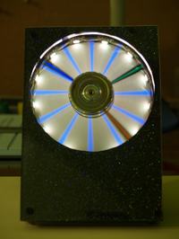
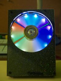
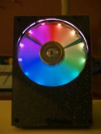
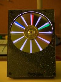
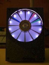
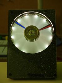
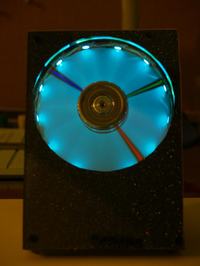
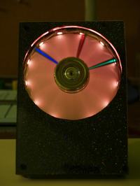
    Today I finished the HDDCLOCK enclosure so I can present the pictures.

    Thanks to the author's help, the watch was able to run - not without small problems.
    The problem that turned out to be the garbage offered by the reflection sensor.
    After again "centering" the plate - as in my disk it is a bit higher up to 1.5mm than the top edge of the disk rotor - everything started working properly.

    I finished the clock before Christmas and from then on I was 4-5 seconds late, ie from 2-04-2010, so it's accurate
    After covering the front you can hear it minimally
    The colors in the pictures are somewhat misrepresented - lighting with fluorescent lamps in my room - workshop and night time :( but what's a bit visible Once again, thanks to the author of the project!
    greetings
    M

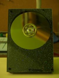
    HDDClock - clock from hard drive HDDClock - clock from hard drive HDDClock - clock from hard drive HDDClock - clock from hard drive HDDClock - clock from hard drive

    HDDClock - clock from hard drive HDDClock - clock from hard drive HDDClock - clock from hard drive HDDClock - clock from hard drive
  • #116 7954162
    Matt_x89
    Level 12  
    Yes ... the clock is idle. The engine does not react at all, I do not even notice vibrations which indicate that the system is trying to start it. I cleaned the layout and uploaded the program again, I checked the BOOTRST bit and still nothing. As for writing a test application, I have not written anything for microprocessors yet. Tomorrow I will put pictures of the system because it currently has a poor camera and better pictures come out in daylight.
  • #117 7954193
    mlassota
    Level 18  
    Matt_x89 wrote:
    Yes ... the clock is idle. The engine does not react at all, I do not even notice vibrations which indicate that the system is trying to start it. I cleaned the layout and uploaded the program again, I checked the BOOTRST bit and still nothing. As for writing a test application, I have not written anything for microprocessors yet. Tomorrow I will put pictures of the system because it currently has a bad camera and better pictures come out in daylight.


    There are two possibilities - or there is no program in the memory of Megi or something is not so much electronics, as well as cold solder on the port of Prock communicating with TDA5140

    After connecting the voltage, the clock starts to rotate - it does not require any command from the remote control.
    As for the remote control it MUST be in the RC5 standard, others will also be read by the infrared sensor but will not be recognized by the processor ...

    What voltage do you have on the 51 processor leg?

    greetings
    M
  • #118 7954247
    Matt_x89
    Level 12  
    On the 51st leg of the Prock, the meter indicates a voltage of 0.02V, sometimes it jumps to 0.03V. I checked this voltage after connecting the power without issuing commands from the remote control. I put the tip of the meter directly on the foot so it excludes cold solder on it. The remote control is a universal pocket for TVs.

    greetings
    Matthew
  • #119 7954275
    mb1988
    Level 12  
    No, no, no, buddy mlassota it worked out pretty well :) . And congratulations on your patience, because as you mentioned without problems, you did not go to ;) .

    :arrow: Matt_x89
    Before I send you the pics I will ask out of curiosity, for sure that you have applied a precision stand under the TDA5140A? Due to the lack of metallization of holes, such a stand is required and it should be soldered on two sides (it is easy to get to know it by the pattern of paths). The same applies to the programming socket, February is also required on the TOP layer.
  • #120 7954299
    mlassota
    Level 18  
    One more question
    Does the processor have a power supply ie between legs 52 or 21 and 22 or 53

    Lack of voltage on leg 51 causes the motor to not spin - the TDA5140 system logic is not powered

    It can be either a damage to the prock or, for example, a lack of connection with quartz or power supply ...

    Remove the TDA5140 chip from the stand and place it back in the cradle, removing the leg 8 out of the cradle.
    Connect the power supply of the clock (5V) and leg 8 with a + 5V wire - If everything is OK with the engine control unit, it should start spinning

    Quote:
    Before you still send pics I'll ask out of curiosity, do you surely use a precision stand under the TDA5140A? Due to the lack of metallization of holes, such a stand is required and it should be soldered on two sides (it is easy to get to know it by the pattern of paths). The same applies to the programming socket, February is also required on the TOP layer.


    I did not take this into account but the fact ... This is the foreground thing!

    Thanks ... If not for help ... just like the previous watch of your design and this one would not be finalized
    PS. How a little bit of "workshop" I think I will take again the Propeller Clock - maybe this time I will give it a try :)

Topic summary

The discussion revolves around the creation of a clock using a hard drive (HDDClock), where participants share their experiences, challenges, and solutions related to the project. The clock operates by utilizing a rotating plate with RGB LEDs that illuminate through a cut-out slot, creating a visual display. Key topics include the design and assembly of the clock, the selection of components such as the TDA5140A motor driver, programming the ATmega microcontroller, and troubleshooting issues like motor control and sensor calibration. Participants also discuss the importance of balancing the disk, the impact of power supply on performance, and the use of various sensors for detecting the slot in the rotating plate. The conversation highlights the collaborative nature of DIY electronics projects, with users providing insights and assistance to one another.
Summary generated by the language model.
ADVERTISEMENT