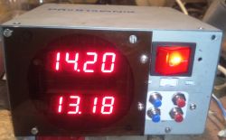
Initially, I had to put all the electronics in the back of the housing, but eventually I decided to have a more compact design.
The engine has no control or smooth speed control. The operating frequency is determined by means of capacitors connected to TDA5140A pins, it also depends on the supply voltage of the motor coils. Synchronization takes place on the principle you provided.
If I did not want to use smooth color adjustment, I would also use Atmega8, that would be enough. But just the introduction of this additional feature forced me to use a controller that has a hardware triple output compare from one meter. In this way, I do not have to play software PWM support. However, I think that with good programming skills, a similar effect could be obtained on Atmega8. In total, I use all available timers in my project: one to measure the time between revolutions, one to measure the time of 1/240 parts of rotation, one to the mentioned PWM and one to count the interrupts coming from RTC with the frequency 4096Hz (very convenient to measure other, necessary in the program, time sequences such as remote control etc.)
In the proclock that I used to do, I used an optoelectronic gap sensor, but the mechanical design looked a bit different there. Nevertheless, it was connected directly to the microcontroller's input and worked fine. In this project I used a reflection sensor and, as I wrote earlier, tests have shown that it will be safer to buffer the signal coming from this sensor. You can finally try to match the resistances in the phototransistor collector circuit and supply the IR diode in the sensor, but I can not guarantee the effects. I also do not think you will have any more problems accessing these elements.


