logo elektroda
logo elektroda
X
logo elektroda
ADVERTISEMENT
Treść została przetłumaczona polish » english Zobacz oryginalną wersję tematu
  • #181 9449957
    mlassota
    Level 18  
    Well, it hurts ... 128 is not cheap ... I wonder if the other elements are alive ...
    If you can not measure the resistance, connect any three wires. Two are definitely OK. Connect the voltage + 5V to 4 and 8 TDA and, of course (-) to the whole system. How it works is OK if you do not de-sold one - and change it with a free one. If you postpone the right move - if it does not return to its place and you take the next one, etc ... In the end will move.
    TDA are quite robust (although it seemed to me that the processors too - not once I connected the voltage backwards but only for a moment).
    greetings
    M
  • ADVERTISEMENT
  • #182 9460930
    hacker_ice

    Level 24  
    I bought the Atmege programmed, but after connecting to the 5V board, nothing moves except the LEDs light up in blue; / what can it be?
  • #183 9462649
    mlassota
    Level 18  
    Show how you have set fisebits. You may not have turned off Atmega103 compliance mode (M103C)
  • #184 9464428
    hacker_ice

    Level 24  
    Yes, I have Fusebits set up, so what can it be? ; / I am asking for advice what I am doing wrong; /

    HDDClock - clock from hard drive
  • #185 9468032
    mlassota
    Level 18  
    hacker_ice wrote:
    I have Fusebits set up so what can it be? ; /

    Good question :)
    Start by checking if 51 is + 5V on the leg - remove it from the TDA stand before checking it. If after 5V the supply voltage appears and the motor does not start, it may mean a TDA failure or incorrect connection of the motor terminals. If the engine is badly connected, you should hear a squeak or the engine should start to "shake". Lack of tension on the 51st leg can indicate:
    - incorrect uploading of the program
    - processor damage
    - quartz damage
    Earlier in the post you have test programs - try to upload them and see if it works on them.
    If you have an oscilloscope or at least some logic analyzer, see if you have a square wave at f = 4,096 kHz on the 7 RTC leg. If it means that rtc is most likely OK - the lack of a signal may indicate:
    - RTC damage
    - processor damage
    - incorrect programming of the processor
    - no communication on the processor lines - RTC
    Desolder MAX - it is unnecessary to start the system.
    Check the entire plate under the magnifying glass for short circuits.
  • #186 9469785
    hacker_ice

    Level 24  
    On the 51 leg Atmega is 5V, the motor does not move, I tried with the other motor from the disc effect the same; / after the test programs the diodes blink :) so the rest I think it's ok? :) it remains to replace TDA and hope that it will start :) and the question is whether the universal remote is needed to run the clock? If so, how to run a watch without a remote control?
  • ADVERTISEMENT
  • #187 9470626
    mlassota
    Level 18  
    Hello
    The watch will start without a remote but ...
    - the watch can not be set
    - it is not possible to change the display mode
    - it is not possible to turn the watch into stand-by mode

    It can be any TV remote control broadcasting in RC5 - some Chinese counterparts from Philips remote controls are great.
    You can also make a remote control yourself by writing a simple program, eg in Bascom on a processor such as AtTiny 2313
    No service is very hard ...
  • #188 9470949
    hacker_ice

    Level 24  
    I am just asking for a test to connect and if I see that in general it will try the pilot :) and how do you think that TDA has gone? ; / defakto already ordered a new system :)
  • ADVERTISEMENT
  • #189 9471023
    mlassota
    Level 18  
    It looks...
    TDA are quite robust but playing with HDD motors has released two pieces, so there is a chance.
    In test programs, colors should ignite one after another and the engine should start for a moment. If he did not move - he did not even murmur - there is a chance that TDA fell
    How do you get TDA, do the same driver on the contact or universal board and connect to the engine ...
  • #190 9501794
    hacker_ice

    Level 24  
    I put in a new TDA chip and the engine does not move; / question if it should go to power with USBasp?
  • #191 9502840
    mlassota
    Level 18  
    So it will not be so easy ...
    Let's start by locating the cause.
    If you have a contact plate, follow the attached diagram and make the controller layout. If you do not have a PCB, then the PCB for the controller is also below.
    How do you connect the controller to 5V - the engine should start.
    As we move on the external driver we will think further.

    PCB is prepared so that you need to solder it on the surface of the DIL18 stand with the pins bent outwards - resistors and capacitors probably you have ...
    greetings

    Scheme
  • #192 9639398
    lolcio
    Level 16  
    Could anyone provide me with a pcb scheme for diodes? Unfortunately, I do not have a protel, and linux probably there is not even ... I made a plate driver for the watch but unfortunately I can not deal with these schamats.
    I would like to ask you some pdf-a :)
  • #194 9704963
    niezabitowski
    Level 11  
    Hello
    Could I ask for the exact symbol of the diodes used in the clock?
    greetings
  • #195 9705654
    hacker_ice

    Level 24  
    They are led from maritex with the designation: LEDP6-S-RGB120-K3
  • #196 9723101
    vegeta3
    Level 10  
    Hello, I'm green in the subject of construction :) . I have a question, is there a chance to buy a ready device?
  • ADVERTISEMENT
  • #197 9923355
    Cobra_Phil
    Level 1  
    There is a Kickstarter project here about a POV clock with a Microchip controller...
    Link
  • #198 10249283
    alex002009
    Level 1  
    Hello misters!
    Доброго времени суток господа!
    I from Russia.
    Я из россии.
    I can not open РСВ a files from archive.HDDClock - schemat i PCB.rar :cry:
    Не могу открыть РСВ файлы из архива.HDDClock - schemat i PCB.rar
    Help?
    помогите пожайлуста?
    For it is earlier grateful!
    за ранее благодарен!
    My mail: alex002009(_at_)mail.ru
    мой mail: alex002009(_at_)mail.ru
    с уважением Александр!
    Yours faithfully Alexander!
  • #199 10332670
    rakso1313
    Level 13  
    I have a problem with opening the pcb file and others using eagle, I only display numbers and numbers, so it's supposed to be done if I have a diagram I've downloaded 10 times maybe someone knows my question?
  • #200 10334170
    niezabitowski
    Level 11  
    These are files not Eagle's only Protel, probably version 99.
  • #201 10334321
    rakso1313
    Level 13  
    niezabitowski wrote:
    These are not just Protel's files, probably version 99.


    Thanks for the answer I am getting ready for downloading protela.
  • #202 10365516
    Anonymous
    Anonymous  
  • #203 10712566
    przemo-9999
    Level 1  
    Hello! You did it in the protel program, or it is possible to run your schema in another program. I can not find a protel
  • #204 10713346
    Pyzaczek
    Level 20  
    I'm sorry, but what time is the clock on the first page on this screen ???
  • #205 10749680
    rogeros
    Level 13  
    The hour from the first page is: 11:41:15
  • #206 10792029
    magnum771094
    Level 1  

    Hello, I am French and I do not understand the Polish and very little mastery English! So, I'm doing the translation with Google. Thank you for your understanding.
    I wish to realize "HHDClock" which is sensational: congratulations for this realization. I have two problems: the diodes "MARITEX" are not available, can I replace them with these LEDs found on Ebay or else at "TME"? Some resistance values are different between the scheme and PCB photos: eg R2-R13-R14 = 47 Ω and on PCB = 100, R1 = 100 Ω and on PCB 150, R3-R4-R5-R11 = 10 k & nbsp; and on PCB 4.7 k, R15-R16-R17 = 10 k & nbsp; and on PCB 47 k's!
    Thank's for your answer. Best regards.

    Hello, I am French and I do not understand Polish and very little mastery of English! So I do the translation with Google. Thank you for your understanding.
     I want to realize "HHDClock" which is sensational: congratulations for this achievement. I have two concerns: the "MARITEX" diodes are not available, is it that I can replace them with these LEDs found on Ebay or another in "TME"? Some resistance values are different between the schematic and PCB pictures: eg R2-R13-R14 = 47 Ω and 100 & 93; = PCB, R1 = 100 Ω and 150 & 93; PCB, R3-R4-R5-R11 = 10 k & nt; and PCB 4.7 k, R15-R16-R17 = 10 k & 937; and 47 k Ω PCB!
    Thank you for your response. Cordially.

    Witam, jestem Francuzem i compend polską i bardzo mało mistrzostwo

    Angielski! Więc robię tłumaczenia z Google. Dziękuję za zrozumienie.
    Chcę zrozumieć "HHDClock", który jest rewelacyjny: gratulacje za to
    realizacja. Mam dwa zastrzeżenia: diody "MARITEX" denies to dostępne,
    Czy to, co mogę wymienić i na te LED znaleźć w domu ebay lub inne
    "TME"? Niektóre wartości rezystancji różnią się między schematem i
    PCB zdjęcia: np. R2-R13-R14 = 47 ] i 100 Ω = PCB, R1 = 100 Ω i PCB
    150, R3-R4-R5-R11 = 10 k & nt; PCB 4.7 k, R15-R16-R17 = 10 K & sub4; i 47k & 937; PCB
    Dziękujemy za answer.Kind.

    CHARACTERISTICS:
     
    Low energy consumption
    IC Compatible
    Intensely bright
     
    TECHNICAL CHARACTERISTICS:
     
    Emitting Color: 3-CHIPS PLCC-6 SMD SMT LED RGB CONTROL MANUAL
    Lens type: clear water
    Wavelenth: RED: 625-630 nm; BLUE: 465-470nm; GREEN: 520-525nm
    Luminous intensity: RED: 6000mcd; BLUE: 5000mcd; GREEN: 6500mcd
    Reverse voltage: 5.0 V
    DC Voltage: RED: 1.8-2 0.4 V; BLUE: 3.0-3.6V; GREEN: 3.0-3.6V
    DC Current: 20mA
    Angle of vision: 120 degrees
    Direct Temp solder: 260 ° C for 5 seconds
    Intensely bright
      
    Angle of vision: 120 degree PLCC-6 Power SMD LED size:
          
    Absolute maximum ratings & agrave; Ta = 25 ° C
      
    Articles Symbol Absolute maximum score Unit
    Power Dissipation PD 100 mW
    DC current SI 20 mA
    Direct crimp * IFP current 30 mA
    Reverse voltage VR 5 V
    Operating temperature Topr -40 ~ 85 ℃
    Storage temperature Tstg -10 ~ 100 ℃
    Set the welding temperature Tsol Max.260 ° C for max. (3 mm from the base of the epoxy light bulb)
      
    * Pulse width of 0.1 ms ≦ duty ≦ 1/10
    Electrical / Optical Characteristics Ta = 25 ° C
      
    Articles Symbol Condition Min. Typ. Max. Unit
    Dissipation of the front VF SI = 20mA 3.00 / 3.60 V
    Invert DC (DC) IR VR = 5V / / 10 uA
    Dominant wavelength D D SI = 20mA / / /
    Luminous intensity IV SI = 20mA / / / mcd
    Power angle of 50% △ θ SI = 20mA / + plusmn; 60-70 / deg

    http://www.ebay.com/itm/20-PCS-PLCC-6-5050-3-...=LH_DefaultDomain_0&hash=item56374973a6Ω
  • #207 11725991
    aleksa809
    Level 2  
    Could someone please tell me :
    1) what jumpers need to be jumped during programming?
    I am getting the square pumping in MAX232 on the 1uF capacitors but RXD and TXD are constant 5 volts?
    I believe that the atmega128 is making those high outputs?
    2) how to configure my computer to be suitable for the programming of this chip?
    I have apsolutely no knowledge on this and Im just trying to make the hdd clock :) , as you could assume i already invested quite a bit of money to get where i am now, so i dont want to see it go to waste because a few glitches :)
    Thanks to anyone who responses :)
  • #208 11734186
    aleksa809
    Level 2  
    HDDClock - clock from hard drive HDDClock - clock from hard drive

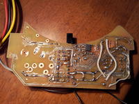
    Here are the images of both sides of the pcb. I know it looks horrible ( It is my first double sided printer transfered SMD board i have ever made :) ) ,but all connections are solid and there are no shorts, the clock chip is missing because i coulnd find it in an SO-8 package but only DIP-8 ,so it will be mounted somewhere in the case, and the PDO jumper isnt where it is supposed to be,but right after it goes out of the atmega,with a little piece of wire ( i will clean it up right after i manage to program it ) and mb1988mb1988 thank you very much for responding, it is an honnor :)

    Again i know it really looks bad but trust me all connections are how they are supposed to be, I've put many many hours into this board :) I've even tried the opto switch op amp output and it is good, but so far it is the only thing that works on the board :(
  • #209 11734385
    mb1988
    Level 12  
    Oh, where to start...

    First of all, 'few glithes' and ''horrible' in your situation sounds like a complement :P .

    What I see is unfortunately lack of knowledge and I don't think that the clock will run near soon, but with small steps maybe someday you will get this working.

    What you call 'jumpers' is in the fact 10-pin programming socket compatibile with ISP programmer which uses KANDA pinout standard e.g. USBasp. You should get one and try to comunicate with your uC. I won't be describing this procedure because it was described many times elsewhere. This step is crucial and can't be skiped.
  • #210 11734415
    aleksa809
    Level 2  
    Yes, you are right, I am just a beginner to this, but hey, everyone was a beginner at a point :) I thought that the max232 is for the programming of the atmega :( , if not, what is it for ? :) And i will fix the pins that you said were for programming by replacing them with a proper socket :)

Topic summary

The discussion revolves around the creation of a clock using a hard drive (HDDClock), where participants share their experiences, challenges, and solutions related to the project. The clock operates by utilizing a rotating plate with RGB LEDs that illuminate through a cut-out slot, creating a visual display. Key topics include the design and assembly of the clock, the selection of components such as the TDA5140A motor driver, programming the ATmega microcontroller, and troubleshooting issues like motor control and sensor calibration. Participants also discuss the importance of balancing the disk, the impact of power supply on performance, and the use of various sensors for detecting the slot in the rotating plate. The conversation highlights the collaborative nature of DIY electronics projects, with users providing insights and assistance to one another.
Summary generated by the language model.
ADVERTISEMENT