logo elektroda
logo elektroda
X
logo elektroda
ADVERTISEMENT
Treść została przetłumaczona polish » english Zobacz oryginalną wersję tematu
  • #211 11734434
    mb1988
    Level 12  
    MAX232 can be used for programming uC but first you have to burn small program into ATMEGA which enables this functionality.
  • ADVERTISEMENT
  • #212 12053275
    bob54
    Level 13  
    Hello
    I have a question whether you also need to upload the eprom file epp to tempos prock.bodajże?
    and whether capacitor values at tda are critical?
  • ADVERTISEMENT
  • #213 12053441
    Anonymous
    Anonymous  
  • #214 12055473
    bob54
    Level 13  
    Thank you for the comprehensive answer, I am in the process of building the device, so everything will be explained soon
  • #215 12056607
    mb1988
    Level 12  
    pretzel wrote:
    In compiled batch to EEPROM there are color palettes to be displayed on the "clock face".
    Unfortunately, a colleague is wrong ;-) . The entire program and data are contained in flash memory. In the "tables.h" file, color palettes with the "progmem" attribute are declared. The eeprom file was generated because I have used the same Makefile file for a very long time, in which there is a command to generate * .epp file. However, in this case it is unused and does not have to be uploaded to the device.
  • ADVERTISEMENT
  • #216 12059118
    Vathaz
    Level 11  
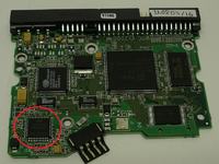
    Hello, I will connect to the topic. I have an old WD100 hard drive (Western Digital 10GB). I removed the motor but after connecting it to the original PCB, as in most drives, it stops after a while due to the lack of reading from the head. How to avoid this? I went over a bit of a topic and only what I found was to connect a 5V power supply directly under the engine speed controller. That is, if you do not look, you could cut the controller with adjacent elements just to operate the engine and it would be the perfect ready controller for operating BLDC motors from hard drives (of course compatible with the number of coils etc. for this driver).

    My question - The motor controller for this disk is ST L6262S 2.6 with 44 pins. I am looking for a datasheet of this driver but I only find drivers with a similar numbering and different number of pins and I can not find the specific one. I need to know the pins to which I connect + - to power the system.

    The sling is the one on the left closest to the engine connector:
    HDDClock - clock from hard drive

    If I could tame the engine right away, then probably more ambitious I would go for a watch based on such a motor :) Does anyone know where this + - connect to this system ? I do not want to burn anything and the pins marked as VCC are a few for sure, the question is from the power supply and not from programming, and which is the mass.
  • #217 12078509
    bob54
    Level 13  
    Hello
    Namely, I have such a problem, after assembling the system, I started programming by USBASP and avrdude with burn o matt, the program read fusebits and set up such as in the figure deselecting bootrst, as it was written when we do not use the bootloader fusbits are written but can not upload hex and I'm always showing error and something like that

    avrdude.exe: error: programm enable: target does not answer. 1
    avrdude.exe: initialization failed, rc = -1
                 Double check connections and try again, or use -F to override
                 this check.

    Added after 1 [hours] 25 [minutes]: < br />

     Did I block the processor?
  • #218 12085054
    bob54
    Level 13  
    Generally with programming I advised, the motor spins sometimes turns on the diodes but I can not set the reflective sensor, I bought 70 inches but I have doubts about it working properly, did anyone assemble it? and maybe use a slit like a mouse with a ball?
  • #219 12085084
    mb1988
    Level 12  
    Hi,
    At the beginning I suggest to try with other values of resistors R6 and R7. I had a problem with choosing resistors and sensor positions myself. Your edge may have a different reflectivity than mine. At the beginning, I suggest to increase R7, e.g. up to 21k.
  • #220 12089701
    bob54
    Level 13  
    Hello
    I managed to adjust the position sensor relatively well, only the clock works backwards but I think it's a matter of reversing the motor phases. The second alarming symptom is that the image fills 1/3 of the disk surface ??? The third thing is the lack of communication with the pilot, the pilot the same as the video in the first post, universal bought for a few zl on alle ... just do not know if he works in Rc 5 how to check it ??? in general, the clock does not show any reaction to the pilot ...
  • #221 12092016
    mlassota
    Level 18  
    My friend.
    The situation is as follows:
    The sensor has not been tuned - that is, it collects a lot of garbage and hence 1/3 of the clock
              - if you have an oscilloscope, check what is going on the comparator - you will know what is wrong
    The remote control works only when the clock is properly activated, i.e. outside the activation function - if it does not work - or it is not transmitted in RC5 either the sensor is not 36kHz or it is released / wrongly connected.

    Does your plate with HDD have a flat side edge or maybe a rounded edge? Do you have no beating in the plane of the plate (as a result of cutting)

    greetings
    ML
  • #222 12116509
    bob54
    Level 13  
    Hello

    My side surface plate has a flat, there are slight beats caused by cutting and a rubber spacer under the plate, I have to get a second aluminum. I have a question for colleagues, can you use a slit sensor here? without modifying the software, it seems that this type of solution is easier to adjust to the correct work
  • #223 12116564
    mb1988
    Level 12  
    Hey,

    The answer is - you can. It is true that I am not convinced that it will not be necessary to introduce a very small modification in the software due to the reversal of the logic of the main interruption in the system. This can be bypassed, for example, by soldering the resistor in the phototransistor emitter instead of the collector. But even without such treatments it should work. Of course, I omit aesthetic values. I deliberately did not use a slit sensor in my project because it would be visible from the front.
  • #224 12117830
    bob54
    Level 13  
    Hi!
    Basically, the reflection sensor gives me interference, when tuning, as soon as the image on the plate appears, it sometimes jumps and flickers, is it related to asymmetry and disc beating?
  • #225 12124903
    bob54
    Level 13  
    Hello
    We managed to tune the reflection sensor, but I have the impression that there is a coupling between the RGB lighting and phototransistor, namely the perfect image is nothing pulsates with the blue dial, but when the color turns red and green begins to pulsate and sometimes breaks the picture .... sounds with which elements of the comparator to experiment?
  • #226 12128496
    bob54
    Level 13  
    Generally, the problem turned out to be the power supply, the motor would slow down when all the LEDs were on. When powering diodes and the rest of two power supplies, everything works correctly :D
  • #227 13755122
    markese
    Level 2  
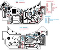
    Hello to all. Congratulations for the fantastic project. I'm beginning to get hold of the necessary components. However I can not understand what are some components that i see the photos. I am attaching the image with highlighted components. I think the diagram not describe it.
    I thank you greatly for your help and patience.

    Excuse me
    the N°1 I think is the TSOP348.
    the N°2 I think is the LM293.
    the N°4 I think is the TCRT1000.

    But what is the number 3 ???

    HDDClock - clock from hard drive
  • #228 13755902
    Brutus_gsm
    Level 25  
    N°1 - IR Receiver TSOP348
    N°2 - RTC DS1307
    N°3 - LM293
    N°4 - TCRT1000
  • #229 13756506
    markese
    Level 2  
    Thank you.
    I have trouble understanding from the photos and schedule what are the different types of capacitors.
    I tried to make a more comprehensive scheme but some capacitors escape me.
    Where I'm wrong? There is a pattern that indicates precisely where are the capacitors?
    I have numbered the various resistors and capacitors, please help me. It's been eight hours that I try to understand in front of my PC.

    P.S. The capacitor N°5 don't exists...my error.

    HDDClock - clock from hard drive
  • #230 13756544
    Brutus_gsm
    Level 25  
    Why don't you use Protel (or Altium) to open PCB and Schematic files? Everything is in the first post of this thread.
    HDDClock - clock from hard drive HDDClock - clock from hard drive
  • #231 13756732
    markese
    Level 2  
    You're my hero and i'm an idiot...I had downloaded protel this morning ... but I had forgotten to those files.
    to program the integrated circuit just connect the card with a serial port to the PC?
  • #233 14843317
    Brutus_gsm
    Level 25  
    You can order it in any PCB manufacturer. First post of this thread contains all necessary files. Find your local PCB manufacturer or try for example http://dirtypcbs.com/
  • #234 15910399
    mnemonic
    Level 11  
    Hello, I will refresh the subject a bit and present the modification of the watch:


    made more than a year ago, works without problems from the first start, maybe a little difficulty makes optimal setting of the reflection sensor, because after some time changes the location, or perhaps the dust interferes with the proper operation.
    From what I remember, I did not introduce many modifications in hardware, definitely more changes were in the program.

    My comments:
    1. It seems to me that the best results can be obtained with a 1.25mm thick plate, I also tested a 0.75mm thick plate, unfortunately the setting of the reflective sensor was difficult, the 1.7mm thick plate generates more vibrations, it is difficult to fit into the casing and it makes noise, but then the correct sensor setting is quite easy.
    2. The thinner the plate gap, the better the resolution of the displayed lines on the dial, the edges of the hands are less blurry, and the animations and colors seem clearer, I was able to cut a 0.6 mm gap.
    3. If you cover the plate gap with, for example, a transparent office adhesive tape, the watch works quieter, at a distance of 1m from the watch in a closed housing, noise is barely audible.
    4. Sample code fragment changing the background:
    Code: C / C++
    Log in, to see the code

    g_speed is a variable that changes like g_position, but with a different speed. You can subtract subtracting from g_position so that you do not run out of data to read from memory, you need to prepare and test your color tables properly.
    5. Recording from a digital camera does not fully reflect the obtained effect. :)
  • #235 16225442
    kerat
    Level 2  
    mnemonic wrote:
    Hello, I will refresh the subject a bit and present the modification of the watch:
    .........
    g_speed is a variable that changes like g_position, but with a different speed. You can subtract subtracting from g_position so that you do not run out of data to read from memory, you need to prepare and test your color tables properly.
    5. Recording from a digital camera does not fully reflect the obtained effect. :)


    Hi, I'm impressed by your craftsmanship and modification. I decided to make this clock. I was able to gather almost all parts. Recently I worked on my version of the PCB. Then I found on Youtube your mod and I thought it would be a good idea to run your clock?
    Sorry for my english, and lot of google translate. Best Regards!
    Milen
  • #236 16235646
    mnemonic
    Level 11  
    kerat wrote:

    Hi, I'm impressed by your craftsmanship and modification. I decided to make this clock and I was able to gather almost all parts. Recently I worked on my version of the PCB. Then I found on Youtube your mod and I thought would you be so kind as to share the software that run your clock?
    Sorry for my english, a lot of google translate. Best Regards!
    Milen


    Hi there,
    unfortunately not,
    I would not share the software, instead I will give you some hints how to animate the clock background.
    Most of my modifications are like "if.. else..", it's easy to play with the code, and make things happen.:)

    Code: C / C++
    Log in, to see the code

    Code: C / C++
    Log in, to see the code

    Code: C / C++
    Log in, to see the code


    Kind Regards
  • ADVERTISEMENT
  • #237 16235719
    kerat
    Level 2  
    Hi, thank you for the replay. Unfortunately I'm not very in with C programming. I just want to make this uncommon clock. But who knows, may I use your fragments of code and see what happend. Best regards.
  • #238 17683007
    lugigann
    Level 2  
    Hello everyone !
    Please tell me the program run only with the loaded bootloader and the bootrst fusebit programmed ?
    The controller does not respond to the command, it's as if it was not programmed.
    On almost all the pins (exlus VCC, GND, XTAL, MOSI, MISO .....) I have 1.9 - 2v.
    Dziękuję ! Wszystkiego najlepszego !
  • #239 17683505
    mnemonic
    Level 11  
    lugigann wrote:
    Hello everyone !
    Please tell me the program run only with the loaded bootloader and the bootrst fusebit programmed ?
    The controller does not respond to the command, it's as if it was not programmed.
    On almost all the pins (exlus VCC, GND, XTAL, MOSI, MISO .....) I have 1.9 - 2v.
    Dziękuję ! Wszystkiego najlepszego !


    Hi there, program can run without loaded bootloader, just change command for fuse bits:
    Code: Dos
    Log in, to see the code


    if you have bootloader, then use:
    Code: Dos
    Log in, to see the code
  • #240 17684597
    lugigann
    Level 2  
    Thank You !
    I tried all the variants and it still does not work.
    The controller is programmed, it has quartz oscillation, IR receiver is ok, ok links.
    Is there a possibility that the firmware is not loaded to the correct address?
    HDDClock - clock from hard drive

    HDDClock - clock from hard drive

Topic summary

The discussion revolves around the creation of a clock using a hard drive (HDDClock), where participants share their experiences, challenges, and solutions related to the project. The clock operates by utilizing a rotating plate with RGB LEDs that illuminate through a cut-out slot, creating a visual display. Key topics include the design and assembly of the clock, the selection of components such as the TDA5140A motor driver, programming the ATmega microcontroller, and troubleshooting issues like motor control and sensor calibration. Participants also discuss the importance of balancing the disk, the impact of power supply on performance, and the use of various sensors for detecting the slot in the rotating plate. The conversation highlights the collaborative nature of DIY electronics projects, with users providing insights and assistance to one another.
Summary generated by the language model.
ADVERTISEMENT