logo elektroda
logo elektroda
X
logo elektroda

uProg - small, fast, portable AVR programmer with SD

manekinen 154828 364
ADVERTISEMENT
Treść została przetłumaczona polish » english Zobacz oryginalną wersję tematu
  • #91 9679012
    leonow32
    Level 30  
    You could do the option to automatically set the fusebits before programming - the point is that if there is a 16MHz quartz on the plate, let the process be programmed using a quartz clock and not the internal 1MHz generator.
  • ADVERTISEMENT
  • #92 9679224
    manekinen
    Level 29  
    tksk2 wrote:
    Or maybe after calling write, read, verifi, and in the same window "delete" and after pressing it will expand the list of files? Followed by selection and "ok."

    Hmm, as it would be an additional option (rather an emergency), I think it will be enough if you call it by pressing two buttons at once (e.g. the middle one) - and confirm it with ok.

    J_Bravo wrote:
    And how is the work with the automatic setting of coffee grounds after programming the processor going? Will it be possible?

    So far, I haven't had when, but if it's easy to do, of course, why not :)

    leonow32 wrote:
    You could do the option to automatically set the fusebits before programming - the point is that if there is a 16MHz quartz on the plate, let the process be programmed using a quartz clock and not the internal 1MHz generator.

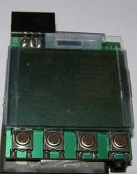
    Hmm, I was already thinking about it, but you would have to store an external fusebit setting for the external 16MHz for each prock. And then come back to the original setting. So I came to the conclusion that if someone has a large batch to upload, he can prepare two TXT fuska files and manually change the timing before programming :)
  • #93 9679361
    mlassota
    Level 18  
    leonow32 wrote:
    You could do the option to automatically set the fusebits before programming - the point is that if there is a 16MHz quartz on the plate, let the process be programmed using a quartz clock and not the internal 1MHz generator.


    The question is how to do it?
    How to tell if there is quartz on the plate? If it changes and it will not be ... you will have to attach ...

    The procedure could look like this:
    Reading fusebits
    If lower than 8MHz - change to 8MHz - internal
    programming
    Return to previously read

    Honestly, I do not really see such a need ... After all, even with 62.5kHż programming does not take forever ...


    One more piece of advice for rockers

    The packaging for elements in SSOP housings is ideal (almost) for holding the display. You need to cut the concave part with a margin of about 1mm.
    It is easy to do ... I recommend it

    This packaging looks like this
    uProg - small, fast, portable AVR programmer with SD

    and the display unit is attached - like this:
    uProg - small, fast, portable AVR programmer with SD
  • ADVERTISEMENT
  • #94 9679612
    J_Bravo
    Level 27  
    manekinen wrote:
    So far, I haven't had when, but if it's easy to do, of course, why not Smile

    It was enough for the card to have a txt (or bascom prg) file with the same name as the in / hex file and the programmer would automatically program the coffee grounds.
    This option would be useful for people who often program pure procki.
  • #95 9679954
    piotrva
    VIP Meritorious for electroda.pl
    mlassota , an interesting idea for assembly, especially for me, because I have some of these packages. I personally will combine something with the use of the original frame, when I come with a petal and parts.
    When it comes to programming fusebits, we have the option of loading them from a file, so ... In my opinion, it would be enough if, for example, finding the same name of the file with the program and the grounds (if the appropriate option is included in the settings) to load these grounds before programming.
    As for determining the presence of quartz, it cannot be done - you have to assume that there is no such ...
  • #96 9680555
    J_Bravo
    Level 27  
    When it comes to Lockbits (or whatever they are called) it's probably better after programming.
  • #97 9680569
    piotrva
    VIP Meritorious for electroda.pl
    No Lockbits are rather after programming, because they are to protect the uploaded program, and each program change in uP (specifically the chip erease function) deletes these Lockbits.
  • ADVERTISEMENT
  • #98 9688920
    piotrva
    VIP Meritorious for electroda.pl
    I assembled uProg yesterday and I had a lot of problems with starting, because I did not solder any capacitor as C5 (with the SD card). After various attempts, I soldered a 22uF THT capacitor (it protrudes "a bit" beyond the LCD) and it started right away. All the time the programmer was powered with 3.4V from lm317. Now I will test and later I plan to add a simple power supply system from a programmed circuit, so far I have not managed to do it, because the zenner diodes, which should be at 3.3V, give a voltage of 2.4V - I do not know why ...
  • #99 9688950
    manekinen
    Level 29  
    That's right. But the 10uF capacitor may be too small - that's why I wrote about it in the description, to give it as big as possible. As you can see, the card needs a lot of instantaneous current during initialization, the three pins of the microcontroller will not necessarily do it - because there is an additional voltage drop on them.

    Also, if someone sees the inscription "SD ERROR", I suggest starting with this capacitor :) If not, then you can check it on another card, you can check the quality of the card socket solders, whether its contacts are not contaminated with flux. And everything should move nicely :) And make sure how the card is formatted or it's best to do the format before booting it.


    // added


    piotrva found an error, when the HEX file does not start with address 0 (e.g. bootloader), the programmer calculates the end address incorrectly and after reaching the end it does not finish programming, but sends data somewhere into space and hangs / loops. I'm working on a fix :)
  • #100 9692416
    piotrva
    VIP Meritorious for electroda.pl
    I also added a modification to my version: On the ISP connector on the CLKO / VCC line, in front of the 1K resistor, I gave a lead that can be connected to:
    a) L1117-3.3C stabilizer, which gives a voltage of 3.3V to power the system
    b) directly to the system power supply (if the programmed system is also at 3.3V)
    Soon I will try to post photos of this modification in the spider style and maybe a schematic.
  • #101 9693727
    manekinen
    Level 29  
    narasta kilka stron temu wrote:
    When it comes to manually setting FuseBits, I think it would be best to enter them character by character in the hex, i.e. first select the first character (two buttons up and down) and then the next one and we have the whole fuse.
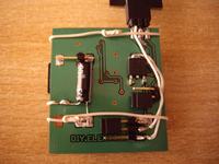
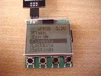
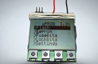
    The program checks the connected processor, and downloads the factory fusses for editing (not those that are stored in the prock).

    I did as you described, it seems convenient. Use the up and down buttons to scroll through the first character of the first note. We press OK, and we go to the edition of the next character of this fuska. OK again, and we go to the first mark of the next fuska. And this way, until the end, there is writing and reading at the end - the fusses read appear in the last line.

    And how? :)

    This option should be used very carefully. Why - probably everyone knows.


  • #102 9695073
    piotrva
    VIP Meritorious for electroda.pl
    As promised photos:
    uProg - small, fast, portable AVR programmer with SD uProg - small, fast, portable AVR programmer with SD
    In the attachment there is a diagram of my modification.
    The SV1 jumper / connector can perform the following functions:
    1. Selecting the power supply through the LDO L1117-3.3 stabilizer from the ISP - CLKO (VCC) connector, an unconnected pin is then a 3V3 power output, it can be connected, for example, with the voltage regulator in the programmer.
    2. Selecting direct power supply - ISP connector pin - CLKO (VCC) connected directly to the 3V3 power supply on the board - this function is useful when the target circuit is supplied with 3v3 voltage - the LDO stabilizer would then cause too much voltage drop
    3. Jumper removed - CLKO pin works as a clock signal output, then connect the power supply from the external system / battery to the appropriate pin of the connector
  • #103 9696020
    chemik_16
    Level 26  
    Great design :)
    As there is a lot of free space on the board - I would suggest pressing the MAX1811 there - a li-ion battery charger - it requires only 2 external capacitors - charging signaling can be given to the prock input, if there is still some left.
    The circuit is available as samples, very popular already; p
    in this way, the question of charging the battery is not an issue.

    edit: of course, as an optional element of the entire structure - when you order more tiles, it would be worth it to be able to expand it :)
  • ADVERTISEMENT
  • #104 9696414
    manekinen
    Level 29  
    piotrva - thanks for the photos, this stabilizer is like it's from there :)

    chemist_16 - yes, if I order another batch of plates, I will put some optional pads for stabilizers or regulators, so that I can solder according to my own. The cost is the same and the possibilities are growing :)

    So yeah, setting the coffee grounds manually works fine. I added file deletion as requested. I added new settings to the config file, fixed the bootloader bug in HEX files, and fixed some other things.

    I am currently working on the correct handling of the atmega2560 and atmega2561 systems, it is not easy, especially because I do not have such systems and my second beta tester does not have too much time to test ... So the software update to 1.3 will be only after we deal with it :) If anyone has the opportunity (and willingness) to test - I invite you to the pw :)
  • #105 9698179
    krzycho123
    Level 31  
    These uPs are not very popular due to the price of ~ PLN 50 / sz and this functionality will not be used too much by users ;)

    I met this uP only with the strongest variant of arduino and there is no need for isp because there is USB and bootloader.

    Personally, I would see a second option for setting fusebits with selecting individual ones - a description of each on the screen.
    To enter the HEX value you need to use a calculator on the PC and it would be additionally easier.
  • #106 9699304
    manekinen
    Level 29  
    Sure it's easier, but you probably don't realize how much code you would have to scratch to do something like this. Virtually every one ucontroller has different fuses or perform a different function - each one would have to write separate descriptions etc. Sure, you can use a memory card for that, but it's too much work, unfortunately.

    Manually setting the coffee grounds took only 300 bytes (because it's super-simple), the version with descriptions ... I'm even afraid to think :)

    I will have the Atmega2560 on Tuesday-Wednesday, so somehow there will be an update :)
  • #107 9699554
    krzycho123
    Level 31  
    I know it's a lot of work with it, but the whole thing could be loaded depending on the selected slingshot from the card :)

    I meant rather a simple description and the ability to switch 1-0 at each, such an additional feature in such perfect equipment as if you wanted to develop it further :)
  • #108 9699575
    manekinen
    Level 29  
    Even if someone took care of the descriptions and prepared a file containing descriptions for each system (believe me, a lot of work, I know what I'm talking about because I was extracting data such as fusses, memory size, or programming type from each datasheet), I still see black stuffing such an option into memory . For such a small processor, it already offers a lot of functions. In the future I will remove the bootloader and in its place I will do Xmega programming with PDI interface, will there be any space - I doubt.

    Krzycho, better show you how the tile came out, because I'm curious :)
  • #109 9699846
    tmf
    VIP Meritorious for electroda.pl
    Have you ever thought about inserting a dataflash memory instead of an SD card and adding USB support? IMHO, a few GB is useless to me, because a reasonable amount of batches can be put in a few MB, while it is quite troublesome to transfer hexes to SD and then insert the card into the programmer. Yes, it would be enough to plug it in and just lose. If it was still seen in the computer as USB Mass Storage, it would be a fairy tale. Note that this solution (USB connection) has one more advantage - this programmer could be used as an ordinary ISP programmer controlled e.g. from AVR Dude and as an independent programmer in the field.
    Second idea - for hexes, the contents of FLASH, EEPROM and coffee grounds must be separate. In turn, the elf structure is too complicated to handle them in a microcontroller, but all HEXs can be glued together, assuming, for example, that FLASH starts with 0x0000, EEPROM from 0x100000, coffee grounds from 0x200000. Then there is only one file containing everything. Such a file is easy to generate by slightly modifying the makefile using the objcopy tool.
  • #110 9699872
    krzycho123
    Level 31  
    mannequin I was just about to throw in, because thanks to your help I was able to solve the problem.

    I had my own boards, after a long search for the cause of the problem, it turned out that the 10uF capacitor is too small to run my mSD cards. The voltage drop was such that only the use of 2x 10uF allowed for the correct initialization of the card.
    It was only possible to fire on the PCB from the author of the design.

    Of course, thank you very much mannequin for help :D

    PS> unfortunately the glue I wrote about, although it was for ceramics, released after 2 days from the glass

    uProg - small, fast, portable AVR programmer with SD
  • #111 9701993
    manekinen
    Level 29  
    tmf wrote:
    Have you ever thought about inserting a dataflash memory instead of an SD card and adding USB support? IMHO, a few GB is useless to me, because a reasonable amount of batches can be put in a few MB, while it is quite troublesome to transfer hexes to SD and then insert the card into the programmer. Yes, it would be enough to plug it in and just lose. If it was still seen in the computer as USB Mass Storage, it would be a fairy tale. Note that this solution (USB connection) has one more advantage - this programmer could be used as an ordinary ISP programmer controlled e.g. from AVR Dude and as an independent programmer in the field.


    Such things are not in bascom ;) And not on such a small prock. But a great idea, instead of a flash memory, leave the good uSD card - and the device could work with it as a portable drive. The option in the menu or holding down the button select whether the device reports as a disk - or as a programmer. If the latter, the display also shows programming details, but this is done from the computer. And that it also supports PDI and TPI. You can dream :)

    Alternatively, add a usb for the uSD card as a colleague is trying to do HERE

    tmf wrote:
    Second idea - for hexes, the contents of FLASH, EEPROM and coffee grounds must be separate. In turn, the elf structure is too complicated to handle them in a microcontroller, but all HEXs can be glued together, assuming, for example, that FLASH starts with 0x0000, EEPROM from 0x100000, coffee grounds from 0x200000. Then there is only one file containing everything. Such a file is easy to generate by slightly modifying the makefile using the objcopy tool.

    Well, with this "group" programming I will think something more, I have to check what fuska files are generated by winavr and bascom - what are the differences. Although uploading them (flash, eeprom, and fusks) to different directories can be tedious and you can get confused. While winavr will generate such a common file, bascom will not. Because even an ELF file can be bitten - why not. Since I support hexes with extended addressing and counting checksums - and different compilers can create these hexes differently and you need to be prepared for some unexpected entries, etc. :)

    And people who tested the programmer constantly reported to me some errors with hex files, and I did not look at such a file, it was built a bit differently or had additional entries, such as "03" or "05", or entries like "02" or "05" meaning extended addressing, placed at the very end of the file - in my opinion, not necessary, because why start another 64kB block of data, if there is no data, there is only the end of the file, ie "01". So there were a lot of additional conditions, comparing addresses, not only that the program has grown, and it will work a bit slower - unfortunately :(

    krzycho123 wrote:
    unfortunately, the glue I wrote about, although it was for ceramics, released after 2 days from the glass

    Or maybe you have chip wrappers, so-called "sticks" such as HERE - this rubber band does not look good, for sure when removing the card or connecting the ISP your display moves to the sides and loses contact.

    A good solution will also be to take 4 tiny copper plates, bend them into the handles, and simply solder to the mass field on the plate, so that they hold the display on the sides - this way the display will be able to slide up to get to the electronics, and the handles themselves should be solid keep it :)

    Well, I wrote it ... :)
  • #112 9702089
    krzycho123
    Level 31  
    mannequin the eraser only for the photo was that it did not work :D as soon as I buy a new Poxipol, it will stick to the whole thing properly because I just have a rest.

    I tried the sample stick, unfortunately the SO8 chip did not work because I would have to put something underneath it and I don't want the plate to break, because it is easy to break the glass - once I smashed the display from 6210 just because of a badly matched plate.

    As for USB, it is unnecessary for me. The Kingston FCR-MRG2 nano reader costs around PLN 6-7 :)
  • #113 9702099
    tmf
    VIP Meritorious for electroda.pl
    Well, in Bascom you can dream it, but if you want to switch to C, I will be happy to help you and I can transfer some fragments to you, e.g. menu, programming, etc.
    As for USB, it is easy to do it, for example on the ATMega U2 series, which have a hardware USB device, and there are mass storage devices. Or give it up and throw in the good FTDI. The costs are small, and such a programmer would be really great. There is also no need to switch anything, because a USB device can report itself as several classes at the same time.
    As for hexes, gluing is simple, even a simple combination of two files will work, worse with coffee grounds. On the other hand, if you think about operating an elf, you are really taking a hoe to the sun. libelf is a dozen or so kB of source code. However, if you want, I can give you my HEX implementation (it is true for PC, but it can be easily transferred to AVR).
  • #114 9702113
    kaeltaz
    Level 16  
    manekinen wrote:
    Such things are not in bascom :wink: And not on such a small prock. But a great idea, instead of a flash memory, leave the good uSD card - and the device could work with it as a portable drive. The option in the menu or holding down the button select whether the device reports as a disk - or as a programmer. If the latter, the display also shows programming details, but this is done from the computer. And that it also supports PDI and TPI. You can dream :)


    If you are low on memory you can always hire atmege128. :-)
  • #115 9702188
    manekinen
    Level 29  
    tmf wrote:
    Well, in Bascom you can dream it, but if you want to switch to C, I will be happy to help you and I can transfer some fragments to you, e.g. menu, programming, etc.
    As for USB, it is easy to do it, for example on the ATMega U2 series, which have a hardware USB device, and there are mass storage devices. Or give it up and throw in the good FTDI. The costs are small, and such a programmer would be really great. There is also no need to switch anything, because a USB device can report itself as several classes at the same time.

    If I ever got inspired by C - that's clear, thanks, I'll take it :) Alternatively, if you wanted to create such a programmer yourself, I will help with the entire ISP, because from what you can see after the corrections - it is not as easy as it seemed to me at first :)

    tmf wrote:
    As for hexes, gluing is simple, even a simple combination of two files will work, worse with coffee grounds. On the other hand, if you think about operating an elf, you are really taking a hoe to the sun. libelf is a dozen or so kB of source code.

    Yes, after the entry "end of file" just check if there is any data and that's it - you can still address them normally, for example for eeprom or even for tea leaves. address 0, data length 3 bytes, no and 3 bytes with a checksum. It might even be a smart solution :) As for the ELF, I must admit without hitting that I did not even look, but if you write like this, I give up immediately :)

    tmf wrote:
    However, if you want, I can give you my HEX implementation (it is true for PC, but it can be easily transferred to AVR)

    Thanks, but I don't think there will be problems anymore. It's just that the variable with the address is of the word type, and you have to be careful not to "twist" when writing / reading the last byte from the hex - under various conditions.

    By the way, let me ask, maybe you have some way to count the amount of data in a HEX file? I count them before saving to see if we have chosen a good file - if it is larger than the memory of the connected probe, the programmer returns the appropriate information.

    Currently, I have it done so that the programmer flies through the HEX file looking for colons. If it encounters an extended address entry, it adds FFFF to the address. If it hits the end of the file, it takes the address and number of bytes from the previous line, adds the address obtained from entries with extended addressing to the address from the previous line, and adds the number of bytes of the last line. And thus the end-of-data address is known. Unfortunately, it has to go through the whole file, and if the file has, for example, 500kB, it takes a while.

    I had this idea to just check the length of the file (after opening it in avrdos such information is immediately available), subtract e.g. 100 bytes from that length, and start checking the file from there. The program will go to the last and penultimate line, add the last address and number of bytes to the last line - and there will be the end address. The method is almost instant - but with one disadvantage. The program will bypass all entries with extended addressing in this way. Hope I didn't mess up too much :)

    kaeltaz wrote:
    If you are low on memory you can always employ atmege128

    Yes, and not only will the PCB not enter it, the cost is rising into space :) Atmega644 already smaller but still too big. Unless there are more procks in TQFP32 with more memory?
  • #116 9702251
    tmf
    VIP Meritorious for electroda.pl
    Unfortunately, if you want an exact hex data size then you have to go all over. On the other hand, you have to anyway, because what if the amount of data is in memory, since it is addressed outside the range of addresses for a given type of processor. So you have to check all the records. By the way, you can also check if the hex itself is correct by preliminary parsing it and checking if the CRC of the records is correct.
  • #117 9702295
    kaeltaz
    Level 16  
    Well, you can always make a pcb sandwich and throw in a bigger atmege.
  • #118 9705191
    manekinen
    Level 29  
    tmf wrote:
    On the other hand, you have to anyway, because what if the amount of data is in memory, since it is addressed outside the range of addresses for a given type of processor. So you have to check all the records.
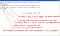
    I mean, I don't check all the records. I do not assume such a terrible situation that the hex file will be addressed in such a way that the older addresses will be first and then somewhere younger / earlier - although it is possible, but I do not know if it is used somewhere?

    Ok, my description was quite twisted, so maybe I will show on a fragment of the file how I get the final address, i.e. the address of the last byte - and knowing it, I know if the batch will fit:
    uProg - small, fast, portable AVR programmer with SD
    The point of reference for the downloaded data are the colons, which unfortunately got cut off when processing the photo quickly.

    This way the file can start anywhere, e.g. bootloader. And I know the address where it ends - I don't need more. When writing to the memory, I load only the data that exists, when writing, the programmer takes the address of the record, the number of bytes, and retrieves bytes one by one until the counter of the number of bytes = the number of bytes of the record. Then it looks for the next colon and this way it goes until address = last byte address (when writing I do not look at additional end-of-data or extended addressing records, I just omit them). Because why read them again.

    I don't know if it's done professionally or not, but it works fine. Unless I come across some flowers in hex files again, it will need to be corrected :)

    tmf wrote:
    By the way, you can also check if the hex itself is correct by preliminary parsing it and checking if the CRC of the records is correct.

    Well, you can, because I read every single character from the file anyway. I will add it to the list, it will probably be added one day :)
  • #119 9705929
    tmf
    VIP Meritorious for electroda.pl
    I think you are counting addresses incorrectly. Note that records 02-05 contain misspelled addresses that you should read, not assume that the address space is linearly addressed. It matters in the code, where you move segments, or create your own segments in memory (BASCOM probably does not have this, so you may not encounter this problem). For example, if a variable is to be in a specific FLASH memory location, then in hex you have a record before and after which there is a "hole" in the addressing. A somewhat fancy problem, but real is sticking two hexes together. For example, I have a hex with bootloader and application code and I want to get the resulting hex. Then, additionally, the order of addressing does not have to be increasing at all.
  • #120 9705989
    piotrva
    VIP Meritorious for electroda.pl
    Well, that's where, among others, problems with my bootloaders, which I honestly accidentally chose for testing, but the problem is actually more complex than just bootloaders.

Topic summary

The discussion revolves around the uProg, a compact and portable AVR programmer that utilizes SD cards for firmware storage. Users express admiration for its design and functionality, highlighting its small size (44 x 39 x 5.5 mm) and fast programming speeds (write: 12.5kB/s, read: 14.5kB/s). Several users inquire about compatibility with various components, such as different LCD displays (notably the Nokia 3310's LPH7779), and the ability to program various AVR microcontrollers, including the ATmega328P and ATtiny series. Issues with SD card compatibility, particularly with SDHC cards, are frequently mentioned, as well as problems related to fusebit settings and display contrast. Suggestions for improvements include adding a battery charging system, enhancing the user interface, and providing better documentation for setup and troubleshooting. The community shares experiences with different configurations, troubleshooting tips, and modifications to enhance the programmer's capabilities.
Summary generated by the language model.
ADVERTISEMENT