logo elektroda
logo elektroda
X
logo elektroda

uProg - small, fast, portable AVR programmer with SD

manekinen 154822 364
ADVERTISEMENT
Treść została przetłumaczona polish » english Zobacz oryginalną wersję tematu
  • #61 9630972
    manekinen
    Level 29  
    Yes, I know the menu works like that. There are no locks there, and you can choose non-existent options (which once existed). I'm working on the menu right now, it will be improved in the next version. And in general, there are quite a few shortcomings in version 1.0, many of them have already been fixed :)

    Do I see correctly that you are using an external power supply? Have you tried to use coin cell batteries?
  • ADVERTISEMENT
  • #62 9633402
    leonow32
    Level 30  
    Hey, and maybe in the next version you will add some buffer with a voltage translator?
  • #63 9633908
    krzysiekdg
    Level 13  
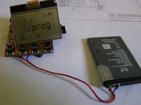
    These cables are not external power supply, only a battery from Sony Ericsson, so far only on the cables, but in the finished project it will be a Nokia 6280 battery because it has the perfect dimensions that fit the board and it will be attached to the programmer board on the back, in addition, I am already charging this battery also from the charger from Nokia. I am still wondering whether not to add a diode signaling the work of the programmer, i.e. one attached programmer, the second diode for data transmission will show whether it is programming and the third diode for charging.

    Added after 35 [seconds]:

    I was also wondering if it would be possible to make Polish in this device?
  • #64 9634030
    manekinen
    Level 29  
    krzysiekdg wrote:
    These cables are not external power supply, only a battery from Sony Ericsson, so far only on the cables, but in the finished project it will be a Nokia 6280 battery because it has the perfect dimensions that fit the board and it will be attached to the programmer board on the back, in addition, I am already charging this battery also from the charger from Nokia.

    Oh, I'm asking because yesterday I checked the programmer's operation on coin-cell batteries.
    Two new CR2032, continuous operation time about 15 minutes. You may say that it is not much, but for such batteries it is really a lot. It is enough to easily update the program in several systems.

    After this time, the voltage drops to 2.6V and problems with the memory card begin. But it is enough for the batteries to rest a little and the voltage returns. It is difficult to turn on the programmer on low batteries, the memory card does not start.

    Also, the battery from the phone is a great choice, and since such a battery has about 4.2V after charging, the easiest way is to connect a rectifying diode in series. There is already a battery voltage measurement in the software - the programmer will not turn on (it will not give voltage to the display and the card) if the voltage is higher than 3.7V. Battery voltage is also displayed at startup.
    krzysiekdg wrote:
    I am still wondering whether not to add a diode signaling the work of the programmer, i.e. one attached programmer, the second diode for data transmission will show whether it is programming and the third diode for charging.

    But why? That's what the display is for. I have a diode from charging, if you prefer, freedom is crazy in your workshop :)
    krzysiekdg wrote:
    I was also wondering if it would be possible to make Polish in this device?

    Someone already asked about it today but the post has been deleted. I do not understand again why? After all, we probably have EVERYTHING related to programming in English. Compiler, whole environment, programmers, tools. Well, maybe the menu will be somewhere in Polish, if someone takes it and Polish.

    Not that this was the only reason, but the introduction of, for example, two languages will be difficult (at the beginning I planned to save all messages in a file on the card so that you could easily edit or replace the entire file and now - the menu is in Czech - but this has proved difficult to do, and there are not enough resources for such exercises.

    leonow32 wrote:
    Hey, and maybe in the next version you will add some buffer with a voltage translator?
    You can make a very simple 6pin adapter with a buffer :)

    Added after 5 [minutes]:

    Oh, I would have forgotten, I got a Chinese today (display of course) and as it turned out the matrix has an organization of 48 * 84 pixels, and the driver is 48 * 102 pixels. Also in practice, the display has 14 characters per line, and theoretically 17. Terrible Chinese technical thought, brrr. Well, but I did itsome code and the programmer supports both types of displays - just select the setting in the file on the card :)

    Added after ... a little longer:
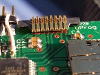
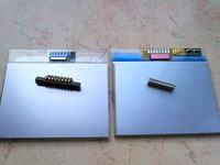
    The display I bought did not have a permanently attached "connector", so when I split the frame it all fell apart.

    On the left the replacement, on the right the original:
    uProg - small, fast, portable AVR programmer with SD

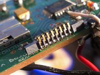
    The joint to the board is soldered in such a way that the movable side of the plates is facing up. You have to struggle with it a bit but you can do it nicely:
    uProg - small, fast, portable AVR programmer with SD uProg - small, fast, portable AVR programmer with SD

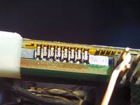
    Well, we add the display, I must be honest that it is SUPER. I used the same clips as before:
    uProg - small, fast, portable AVR programmer with SD

    And there is also a metal display frame, it looks like it can be used nicely to attach the display, so you will not need a housing. I'll tire her out yet :)
  • #65 9638384
    manekinen
    Level 29  
    Update No. 1

    PCB v1.1
    -added current limiting resistors for MOSI and SCK lines - 22? (my previous suggestion, 330?, is definitely too much)

    Soft v1.1
    -fixed a bug where the programmer crashed after waking up from sleep mode
    -removed the low voltage error for LCD (contrast problems)
    - EEPROM read / write errors from HEX files have been removed
    - communication errors removed (SPI setting)
    -fixed menu bugs where non-existent options could be selected
    -removed a bug showing a broken progress bar with the auto verification option turned off
    -removed a bug with not working animations (only the first frame appeared)
    -removed inconsistency between the program and the chip.db base, the "programming method" byte was "misunderstood" by the program
    -added support for displays with 48 * 102 driver (see file "config.ini")
    -added contrast and bias adjustment for LCD (see file "config.ini")
    - battery voltage measurement has been added - protection against switching on above 3.7V
    -general code fixes

    Many thanks to my colleague mlassota who spent a good dozen / tens of hours testing.

    Overall, a lot of corrections, but everything should work as it should.

    The battery voltage will be displayed all the time in the first line of the screen, but it will be refreshed only when navigating through the menu - so that the program does not constantly have data to the LCD.

    The "config.ini" file has changed, so you have to set it your way and upload it to the card.

    In the next version I will add, among others extended addressing of HEX files, so far the limit is 64kB - wonders can happen above.

    Before uploading a flash, please read the THIS LINK
    Attachments:
  • #66 9638712
    krzysiekdg
    Level 13  
    After uploading the hex itself, the slingshot died in his shoes? what could have happened now, there is no communication with him and the software was fully loaded without a problem.
  • #67 9638747
    manekinen
    Level 29  
    Describe exactly how you connect the programmer with the threshold.
    Power supply voltage, battery or power supply?
    What programmer? What voltage on the programmer?
    And most importantly - have you soldered additional resistors to the board, which I wrote about recently?

    Because, I will write it again: the chip HAS NO SUCH POSSIBILITY to die after loading flash. On the other hand, programming a system powered with 3.3V 5V signals often ends up with the burnout of that system, especially with a large load. I guess I'll have to do some little how-to.

    I just uploaded the batch again at home and everything is fine.
  • #68 9638769
    mlassota
    Level 18  
    Colleague Did you modify the equipment? Resistors on the SCK and MUST are essential
    I additionally gave a 3.3V zener diode, but my colleague tested it without diodes and it was ok too
    How did you update soft? Bootloader or programmer?

    And you warned me ;)


    Regarding the problem - you have a card in the slot - take it out and run it - maybe it's the contrast?
  • ADVERTISEMENT
  • #69 9638844
    krzysiekdg
    Level 13  
    I have a battery from Nokia charged at 3.9v, the stabilizer has 3.3v, which goes to the whole system.
    I programmed usb isp via khazam.
    After finished programming, nothing was displayed on the LCD, I plugged into the usb and can not see the system anymore (there is any chance to save it, as long as nothing is hot?)
    I programmed the second atmege through bascom and the computer communicates with it, but the system does not display anything anymore and I do not know how to set the lcd well, I have the one that was displayed in the description in the previous flash.

    Added after 1 [minutes]:

    I didn't solder anything, I just uploaded a flash to the previous board

    Added after 1 [minutes]:

    you can't see anything with or without the card
  • #70 9638902
    manekinen
    Level 29  
    You see, I asked how did you connect the programmer with the threshold. You did not write.

    I prepared two nice pictures which probably explain a lot by themselves, I didn't think it would be such a problem, so I didn't mention anything about it at the beginning.

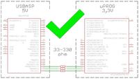
    How to program a 3.3V powered system with a 5V programmer:
    Why can't 5V be applied to the target ?:
    uProg - small, fast, portable AVR programmer with SD

    The maximum voltage that can be given to each pin (after the reset pin) is V CC + 0.5V . So in our case this is it 3.8V . We have to get rid of yet 1.2V , and we do it like this:

    uProg - small, fast, portable AVR programmer with SD

    The excess will flow through the internal pin and resistor protection diode, nothing bad will happen. This is a simplified version, the buffer should be used correctly to convert the voltage level.

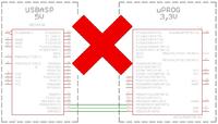
    How NOT to program:

    uProg - small, fast, portable AVR programmer with SD [at]

    Direct connection will damage the ports!
  • #71 9638916
    krzysiekdg
    Level 13  
    So the answer is probably simple I am one bone in the back ehh what what, but I already know how to connect and program with different voltages :D
    only a miracle that the other survived :D
    what about the display setting? Will it work immediately after uploading the flash or do you need to set something else?
  • ADVERTISEMENT
  • #72 9638942
    mlassota
    Level 18  
    in the config.ini file you have a contrast setting - I don't remember what it is by default - but on c8 you can see something ... I think I have bc and you can see it nice but you have to choose
  • ADVERTISEMENT
  • #73 9638944
    manekinen
    Level 29  
    Hope you read the description in the attachment? File "config.ini" has changed. You have to upload it to the card and set it up. From what I can see, the display setting with the 48 * 102 driver (Chinese) was selected after my play, turn it off if you have a 48 * 84 display (and you probably have one).

    AHA and in fact, you will have to choose the contrast because each LCD reacts differently. You have to shoot into a fairly narrow range, for me the adjustment is from A0 to B4 - when I go out, it's either dark or light and you can't see anything. Remember that this is in HEX format. Decisively, the adjustment is from 128 to 255. Turn on the windows calculator, switch to scientific mode, enter a value, and switch to "HEX" :)
  • #74 9639049
    krzysiekdg
    Level 13  
    It seems that the second atmega was also damaged because on the previous flash, ver1 also does not display anything and what is worse, the system does not turn on.
    now I have to invest in processors again.
  • #75 9642540
    mysz234
    Level 10  
    Will you sell the finished device? I would like to buy assembled and ready for use.
  • #76 9642803
    drzasiek
    CNC specialists
    Why don't you set the contrast on the device? Everyone would set themselves up (additional option in the settings), write eepromia and that's it ... just one 1-byte variable that you send as a command when initializing the LCD, in C it would be literally adding a pair of 5-6 lines in the entire code, no I know about BASCOM, probably less?
  • #77 9643856
    krzycho123
    Level 31  
    I also wanted to propose it, as you mentioned yourself that each LCD interprets the contrast differently, maybe it would be worth including some regulation in the code, eg only "up" in some simple way, e.g. holding down 2 keys after switching on?
  • #78 9644342
    manekinen
    Level 29  
    Thanks for the tips, but I've already thought about this issue. We only adjust the contrast once, at startup. After that, this option will be completely redundant. Another reason is that the whole menu is optimized so that adding 6 options in the settings and, in addition, setting more / less, will force larger changes in the code and its enlargement. But I will write the hint, of course, maybe it will be added one day :)
  • #79 9648693
    mlassota
    Level 18  
    Hello colleagues

    As I made this arrangement some time ago, together with a colleague mannequin we have been testing since version 1.0.1.

    Originally my version looked like this: uProg - small, fast, portable AVR programmer with SD

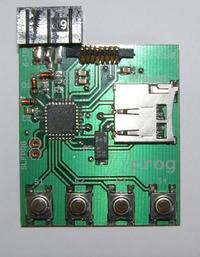
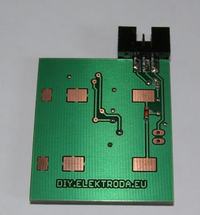
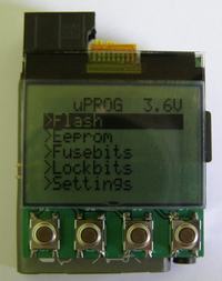
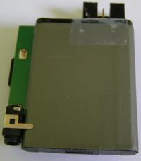
    Friend mannequin he sent me a "factory" board to make the final version of the programmer. Of course I took advantage of it and here is what came into being:

    uProg - small, fast, portable AVR programmer with SD uProg - small, fast, portable AVR programmer with SD uProg - small, fast, portable AVR programmer with SD uProg - small, fast, portable AVR programmer with SD

    I also post programming videos "in layout".


    Now the sensations.
    The programmer is perfect. I program very fast. The reading function allows you to save the program on the card, e.g. before updating the program in the target device.
    Programming errors practically do not occur - unless the plug is disconnected from the programmed circuit :)
    The battery from a mobile phone (some Samsung - it was about dimensions) works very well. Connected to the programmer through the 4148 diode (SMD visible on the bottom side of the board) to lower the voltage to 3.6V. It will last a long time - after 12 hours of switching on and several dozen programmed processors it dropped by 0.1V. I also added a socket to the charger from Nokia (old), but you need to check the voltage of the unloaded - max 5.5 V (a drop on the 0.6V diode gives 4.9 per processor - and it is still safe - in sleep due to the practical no load on the processor can go higher voltage and 5.5V will withstand) YOU MUST REMOVE THE SD CARD

    What more to write. It is simply a revelation!

    I heartily recommend it, a friend mannequin Congratulations once again on a great project

    Regards
    M.
  • #80 9661413
    Snikers
    Level 24  
    Can you ask for a fragment responsible for operating the display? I'm trying to fit in medze8 (I make a digital-controlled laboratory power supply on such a display and I exceed the bone capacity by 8%).
  • #81 9661767
    manekinen
    Level 29  
    Display support based on https://www.elektroda.pl/rtvforum/topic487530.html#2496320

    I threw out unnecessary functions, I slimmed down a bit because in its current form it takes a lot of flash. Except that this code creates an image for the display in RAM, and it needs 504 bytes.

    But if that's the code you meant, the most memory consuming thing is calling functions with parameters, for example
    Code: text
    Log in, to see the code

    Where whole two bytes are unnecessarily transferred. If we call such a function several times in the code, the code really grows before our eyes. These two bytes are whether we want negative text, and the second is whether we want a double-sized font. They are rarely used. It is better to declare two bits in memory and if necessary switch them manually as to transfer whole bytes, that is:
    Code: text
    Log in, to see the code

    And in the function Lcdstr delete them.

    In the appendix, a slightly changed program (only functions, you have to declare them - e.g. in the main file - in the original link is shown what and how). Not everything yet, because I make changes successively when I start to run out of space :) In function Lcdupdate added piece of code that causes the data to be displayed correctly on the displays with the 48 * 102 driver (I send an additional 18 bytes at the end of the line). Function Lcdline looks terrible, so much counting to display the line - I'm definitely going to do something about it. There is also a bitmap display function, to understand this you need to open the display datasheet and the BMP file structure description.
    Attachments:
  • #82 9661851
    Snikers
    Level 24  
    Oh, it's the same code. I use a large font. I do not have any graphics, and I put small symbols into the font for special characters. With a function call
    Code: text
    Log in, to see the code
    I struggled to get it where it was needed, and a few other routines that were kicked out took 30% of my memory away.

    Thanks for the NEGATIVE homing, I don't actually use it. I will attach a large font externally, draw what should be large, then small and the same.

    ps. for the eye in the current stabilization mode in the prototype on medze16
    uProg - small, fast, portable AVR programmer with SD

    Added after 4 [minutes]:

    btw.
    Code: text
    Log in, to see the code

    I think you can shorten it in the same way. like STRa [/ code]

    Added after 15 [minutes]:

    I pushed and it's 97%, thanks again.
  • #83 9661942
    manekinen
    Level 29  
    Yes, you have to throw out Lcdfontsize and Ch_inv. Because they are passed by several functions to the one that actually uses them. From the code I fired some unnecessary mathematical operations, I replaced some divisions and multiplication with shifting bits (compare the codes), but for sure a lot can still be saved. I used this ready because I wanted to focus on the ISP and programming itself, I know it is not very optimal. If you want to, put a topic in the appropriate section, then maybe we'll get something more out of it together :)
  • #84 9664799
    Snikers
    Level 24  
    These are the prefabs, not to do doctorates in the periphery, but to focus on the main functionality. The disadvantage of the cooker is that it usually contains everything, so it is not optimal.

    It analyzes the code and I have a few insights.
    Interesting replacement of SPIOUT with references to registers, I have not encountered this before. (I checked, it doesn't compile. It's probably for hardware SPI?)
    FOR NEXT is more resource consuming than DO LOOP UNTIL? (I checked - saves 8 bits)
    I do not understand the shipment to the frame, I have to trace the note atmegi
    Is there a big difference between X = X-1 and the decr X? (I checked and X = X-1 takes 4bytes less after compilation than decr X)

    I don't use LCDPIXEL but I can see SHIFT OFFSET is there
  • #85 9666233
    manekinen
    Level 29  
    SPIOUT was a software SPI. UDR is a UARTA buffer, in this case the uart works in the "uart in spi mode" - that is, I have two fully functional hardware SPIs - and the LCD works on such SPI together with the memory card. Atmega328P makes it possible, the compiler will surely crash the Atmega8.

    Added after 4 [hours] 18 [minutes]:

    Update No. 2

    Soft v.1.2

    -fixed incorrect addressing of last word in 128kB procks, uprog addressed it with "0000" instead of "FFFF"
    -fixed bug with progress bar for files larger than 64kB
    -fixed a bug with the progress bar when saving small files to large prock
    - button delays when navigating in the menu have been improved
    -added support for extended addressing of IntelHEX files - read and write (no 64kB limit). The files created are identical to those created by AVRDUDE while reading.
    -Added 1 second delay when turning on if the battery voltage is below 3V (this helps to initialize the SD card by charging the capacitor for longer)
    - programming speed test (signature reading) is now performed 100 times, higher chance of detecting too high speed / errors with a long tapeworm (the test is very fast, you can't see the difference)
    - "success" animation has been added, it is played after successful saving / verification, provided that animations are turned on.

    Chip.db v.1.02 prock database
    -I completed almost all entries, there are also grandparents from the AT90S series and a few attins.

    I'm going to add a PDI interface for XMEGA procks. But first I need to get one such copy and a piece of the programmer for it. Unfortunately, it will be implemented programmatically and it probably will not surprise you with the speed of an ISP, but we'll see what comes out of it :) And even the socket fits, 6pin PDI = 6pin ISP.

    I already have displays, tiles soon :)

    I will add a video from Atmega128, but it was recorded earlier and it does not show operations on HEX files. But you can see the programming speed, the test gave the same results as I got on the Atmega644 - write 12.5kB / s, read 14.5kB / s.


    Before uploading a flash, please read the THIS LINK
    Attachments:
  • #86 9670140
    tksk2
    Level 11  
    Hello.
    The programmer works great, nods to the author. And I also have this suggestion: to be able to delete files from the card, of course, from the programmer level.
  • #87 9670924
    manekinen
    Level 29  
    Thanks :)

    The idea is also good, there are often so many of these files that I have to scroll through a few pages before I find what I need. Deletion itself is not a problem, it can be done while normally browsing the files - but how do I invoke them? Any combination of buttons?
  • #88 9670936
    studzin
    Level 17  
    The button combination and confirmation will be ok.
  • #89 9674407
    tksk2
    Level 11  
    Or maybe after calling write, read, verifi, and in the same window "delete" and after pressing it will expand the list of files? Followed by selection and "ok."
  • #90 9677515
    J_Bravo
    Level 27  
    And how is the work with the automatic setting of coffee grounds after programming the processor going? Will it be possible?

Topic summary

The discussion revolves around the uProg, a compact and portable AVR programmer that utilizes SD cards for firmware storage. Users express admiration for its design and functionality, highlighting its small size (44 x 39 x 5.5 mm) and fast programming speeds (write: 12.5kB/s, read: 14.5kB/s). Several users inquire about compatibility with various components, such as different LCD displays (notably the Nokia 3310's LPH7779), and the ability to program various AVR microcontrollers, including the ATmega328P and ATtiny series. Issues with SD card compatibility, particularly with SDHC cards, are frequently mentioned, as well as problems related to fusebit settings and display contrast. Suggestions for improvements include adding a battery charging system, enhancing the user interface, and providing better documentation for setup and troubleshooting. The community shares experiences with different configurations, troubleshooting tips, and modifications to enhance the programmer's capabilities.
Summary generated by the language model.
ADVERTISEMENT