logo elektroda
logo elektroda
X
logo elektroda

uProg - small, fast, portable AVR programmer with SD

manekinen 154822 364
ADVERTISEMENT
Treść została przetłumaczona polish » english Zobacz oryginalną wersję tematu
  • #31 9603187
    narasta
    Level 21  
    When it comes to manually setting FuseBits, I think it would be best to enter them character by character in the hex, i.e. first select the first character (two buttons up and down) and then the next one and we have the whole fuse.
  • ADVERTISEMENT
  • #32 9603611
    manekinen
    Level 29  
    narasta wrote:
    When it comes to manually setting FuseBits, I think it would be best to enter them character by character in the hex, i.e. first select the first character (two buttons up and down) and then the next one and we have the whole fuse.


    I will seriously consider this option, because there will be a lot of character scrolling (from 0 to F), but I would have to optimize a little code because there is only a little free space left, probably 400 bytes.

    And a small correction to all of them - I asked NOT to ASK about the tiles here! NOT AT PW! (I think I got 20 already). This is not a place for such things. Unfortunately, I will report such posts. You want to put it on a topic somewhere and write about the tiles there.
    Someone (jealous?) Reported that I run some trade here - thanks to your questions about pcb - AND THIS IS NOT AND WILL NOT BE. I think I made myself clear in the first post.
  • #33 9604898
    farrix
    Level 17  
    Hello!

    After 1 is a very successful project (in general, the last page of the diy is striking in the eyes (positive, of course))
    After 2, I have a question if my friend would not like to do something like his colleague Freddie Chopin did with his jtag, that you could order plates with sets of parts, or a set without a display, sometimes a stupid smd capacitor can piss you off when we have 1206 instead of size 0805?
    After 3, I have a question for a friend about charging li-ion (poly) batteries, do you need to control the charging yourself or there is a control system in the battery and just connect the power supply (or what voltage)
  • #34 9605179
    george2002

    Level 21  
    I will say this: AWESOME! and written in Bascom well, it's just amazing, I have a little hunger because my friend stole my business from under my nose because I once wanted to commit such a programmer, but returning to the film, firstly: very neat, although some housing would be nice, secondly very simple and in my opinion the through-hole version is not unnecessary, there are practically only 2 elements heavier to solder - atmega and sd socket and the rest is without sadism on stubborn transformer you can solder ;) third, simplicity and speed - especially speed! and especially a very nice programming speed detection mode :) I could write more but these are the most important things for me

    PS1.
    What library does my colleague use in Bascom to support SD? I assume that from the new one that has recently been written by a man for free? or with AVR-DOS?
    Oops I read on the website and I conclude that it is AVR-DOS but the plans are for a better version ;)

    PS2.
    It would be nice if you could change the coffee grounds through this programmer :)

    PS3.
    You can add programming time under the progress bar - very nice and useful thing and I doubt if it messes the program / speed :) it would be even better to write time to complete programming :)

    PS4.
    It is possible to get the uncompiled version as a BAS file ;) ?


    Best regards, congratulations on vg and a useful project! - of course, the vote was cast because in my opinion it was very well deserved :)
    George2002
  • #35 9606153
    manekinen
    Level 29  
    george2002 wrote:
    What library does my colleague use in Bascom to support SD? I assume that from the new one that has recently been written by a man for free? or with AVR-DOS?
    Oops I read on the website and I conclude that it is AVR-DOS but the plans are for a better version
    Yes, AVR-DOS. The new one is KokkeKat. Free even for commercial use. But I didn't feel like changing it anymore, and the project is 100% free anyway. SDHC is also for AVR-DOS, that's what I meant. The issue of replacing the file and testing, perhaps it will be in the next update - although I do not know why an 8GB card for storing 32kB files is for ;)

    george2002 wrote:
    It would be nice if you could change the coffee grounds through this programmer

    But you can, just create a text file with the saved values :) As for the manual change, we'll see :)

    george2002 wrote:
    You can add programming time under the progress bar - a very cool and useful thing and I doubt if it messes with the program / speed, it would be even better to write the time to finish programming

    He's going to mess up. I wanted to add a percentage ratio - but too much fun / too much code / too slow. And time is already quite a lot of fun. The rest of the programming does not take a few minutes, so you have to wait for some seconds. The program would not even have had time to estimate the remaining time, and the programming would be over.

    george2002 wrote:
    Is it possible to get an uncompiled version as a BAS file?
    No, I already mentioned that. However, if someone is interested in the details of the implementation of individual functions, I can show what is done and how.

    I reported posts about tiles again. Again, someone reported that there is some trade going on here. If this is what the social activities on this forum look like, thank you very much! I hope the moderator will take the appropriate consequences for these people, because I'm sick of it.
  • #36 9607450
    piotrusgit
    Level 12  
    Hello,
    I have a few questions:
    1) If I read it correctly, is it possible to upload only one version of the program to the programmer?
    2) Is your colleague going to make the option of selecting a file for programming? For example, I upload 10 programs to uProg and choose the current version on the spot
    3) Is it possible to download the program from the microcontroller connected to the programmer (backup)
  • #37 9607844
    piotrva
    VIP Meritorious for electroda.pl
    1) There can only be one firmware version on the programmer
    2) it is written that in the uProg programmer there is an SD card with many programs, and in the menu we choose which program we want to upload to the programmed system
    3) yes, as long as the processor from which we want to read the program is not read-protected with Lock Bits
  • #38 9608384
    farrix
    Level 17  
    I have one more question for my friend, could my friend share (or send me via e-mail) a piece of bootloder responsible for programming the atmega flash memory, I mean exactly to which registers the colleague sends, what packages (the point is that you have to send to flash by pages) , and what also needs to be scratched in assembly language.
  • ADVERTISEMENT
  • #39 9608417
    Klima
    Level 31  
    Could you describe the method of mounting the display in more detail?
    As for the device itself - it looks amazing. However, I believe if it had an additional STK500 emulation it would have been even better. You could use FT232RL.
  • #40 9608854
    manekinen
    Level 29  
    piotrusgit wrote:
    1) If I read it correctly, is it possible to upload only one version of the program to the programmer?
    2) Is your colleague going to make the option of selecting a file for programming? For example, I upload 10 programs to uProg and choose the current version on the spot
    3) Is it possible to download the program from the microcontroller connected to the programmer (backup)

    Please read the description carefully. I know it's very long and maybe you can get a little lost, but it's really there. You can upload any number of HEX or BIN programs to the card and select them from the list. The contents of the system can also be read to a file on the card, files with a sequence number are created. As far as I remember, you can create 255 of them, but if someone needs more, I can increase the number to 65535. So the so-called backup can also be done. The posted video explains a lot.

    farrix wrote:
    I have one more question for my friend, could my friend share (or send me via e-mail) a piece of bootloder responsible for programming the atmega flash memory, I mean exactly to which registers the colleague sends, what packages (the point is that you have to send to flash by pages) , and what also needs to be scratched in assembly language.

    As for the bootloader, for the purposes of this project I modified the original bootloader of the avr-dos developer to fit 4kB (because it took up about 7kB). Here are the sources of the bootloader with the modified library: http://www.mcselec.com/index2.php?option=com_forum&Itemid=59&page=viewtopic&p=47233#47233
    I tested on Atmega32 and Atmega328P. But if my colleague just wants to write something to flash memory, there are also examples in the bascom help.

    Klima wrote:
    Could you describe the method of mounting the display in more detail?

    Exactly what? How did I make these handles? Because this display is only held on the handles. There is no need to describe it too much, it is a fragment of such a plugin:
    http://sklep.avt.pl/photo/product_info/4/b/e/1_4be6aaab5d20.jpg
    I do not remember whether male or female, but one of them has these partitions, exactly 5.2 mm wide, and this is the perfect width to catch the display with the plate. It is enough to saw off what is needed and sand it nicely. After that, the display lies on the SD card slot and a contact eraser. The left side is hanging in the air, but you can stick something on because there is too much pressure and you can say goodbye to the display :(
  • #41 9609267
    Klima
    Level 31  
    manekinen wrote:
    Klima wrote:
    Could you describe the method of mounting the display in more detail?

    Exactly what? How did I make these handles? Because this display is only held on the handles. There is no need to describe it too much, it is a fragment of such a plugin:
    http://sklep.avt.pl/photo/product_info/4/b/e/1_4be6aaab5d20.jpg
    I do not remember whether male or female, but one of them has these partitions, exactly 5.2 mm wide, and this is the perfect width to catch the display with the plate. It is enough to saw off what is needed and sand it nicely. After that, the display lies on the SD card slot and a contact eraser. The left side is hanging in the air, but you can stick something on because there is too much pressure and you can say goodbye to the display :(


    So it is not permanently attached in any way? Only pressed in with these latches? Sits firmly and steadily enough? After all, it's supposed to be a portable device.
  • #42 9609282
    manekinen
    Level 29  
    It seems I wrote earlier ... you can catch it with double-sided tape - because the only thing that threatens him is moving to the side and losing contact on the pins. I did not stick it at home, because I take it off every now and then and rummage it in something, but in the finished device, it is worth somehow securing it. Maybe someone will find a better idea for mounting? So now I thought you could use the original metal frame, bend it properly, and solder it to the board :)
  • #43 9609327
    farrix
    Level 17  
    Oh, so I will have to dig up some of these codes, because I did not mean a ready library, but rather the idea of writing data to flash, if I mastered it, you can bootloader on practically everything, on 1wire, i2c, and it will even be delivered to a usb implementation of the barrel design in c.
    Therefore, if a colleague has some knowledge on this subject, or knows the pages about it, I would be grateful.
  • #44 9609609
    J_Bravo
    Level 27  
    I suggest to add the fusebits / lockbits programming option automatically after Flash programming.
  • ADVERTISEMENT
  • #45 9610011
    krzysiekdg
    Level 13  
    I also join the proposal if it is possible, It will make things easier for many inexperienced beginners.
    Automatic setting of fusebits of the programmed circuit by the programmer.
  • #46 9610209
    manekinen
    Level 29  
    farrix wrote:
    Therefore, if a colleague has some knowledge on this subject, or knows the pages about it, I would be grateful.

    I can't help you on this subject because I used the ready-made ones. But if there are any questions about ISP programming, feel free to ask (it's best to set up a topic in the appropriate section).

    J_Bravo wrote:
    I suggest to add the fusebits / lockbits programming option automatically after Flash programming.

    krzysiekdg wrote:
    I also join the proposal if it is possible, It will make things easier for many inexperienced beginners.
    Automatic setting of fusebits of the programmed circuit by the programmer.


    But where is this automation going to come from? I mean, how should the programmer know what settings to save? I've never used options like this so I don't know. Compilers automatically generate additional fusic files?
  • #47 9610240
    krzysiekdg
    Level 13  
    A question from a different barrel - does this programmer have the option of repairing wrongly set fusebits?
  • #48 9610265
    manekinen
    Level 29  
    It can save factory cards (option fusebits> defaults), but if you block ISP communication, it will definitely fail. Because you are probably asking about the functionality of Atmega Fusebit Doctor? I would like to add that the ISP to HV translation device is already on the desk. However, due to some difficulties in reconciling the two protocols, I do not know if he will see the light of day :(
  • #49 9610416
    leonow32
    Level 30  
    manekinen wrote:
    J_Bravo wrote:
    I suggest to add the fusebits / lockbits programming option automatically after Flash programming.

    krzysiekdg wrote:
    I also join the proposal if it is possible, It will make things easier for many inexperienced beginners.
    Automatic setting of fusebits of the programmed circuit by the programmer.


    But where is this automation going to come from? I mean, how should the programmer know what settings to save? I've never used options like this so I don't know. Compilers automatically generate additional fuska files?

    No problem - the coffee grounds are in a file with the same name but have a different extension. For example, the program is in the PROGRAM.HEX file, the grounds in PROGRAM.FUS, and the eeprom could also be automatically loaded from PROGRAM.EEP
  • #50 9610440
    manekinen
    Level 29  
    What program does it generate? WinAvr? The fusebit file is probably just a regular BIN, but with the FUS extension? I would like to upload a sample file like this, I would like to preview it :)

    An interesting proposal, when uploading a flash file, the programmer would check if there are files with the same name in other folders and automatically upload them :)
  • #51 9611573
    Lewho
    Level 15  
    Perfect design!

    If I had something like this two years ago, I would not have to drive almost 600 km to upload a new batch to the client (my error in the program), but I would send him such a miracle and he would do it myself :)

    The programmer would certainly prove useful in production.
    If you are still thinking about further modifications, please add a counter for the programmed circuits and an LED / buzzer output signaling an error while programming the circuit.

    Congratulations and best regards.
  • #52 9611897
    J_Bravo
    Level 27  
    manekinen wrote:
    What program does it generate? WinAvr? The fusebit file is probably just a regular BIN, but with the FUS extension? I would like to upload a sample file like this, I would like to preview it :)

    An interesting proposal, when uploading a flash file, the programmer would check if there are files with the same name in other folders and automatically upload them :)


    The point is not to program new integrated circuits into Flash programming, then programming Coffee grounds only as in, for example, Bascom with the directive
    $PROG &HFF, &HE2, &HDF, &HF8 
    Coffee grounds automatically programmed after uploading Flash.
    Bascom creates a special file with the extension name.prg with the contents:
    FF
    E2
    DF
    F8
    
  • #53 9621762
    krzysiekdg
    Level 13  
    I have such a question
    1.If I upload the hexa to this atmega 328p, will the system work immediately?
    From what I saw, it is impossible to set fusebits in it.

    2. Will the system work without a memory card with the necessary files on that card?
  • #54 9621903
    mlassota
    Level 18  
    Quote:
    1.If I upload a hex to this atmega 328p, will the system work immediately?

    Almost there - you just need to configure the CPU
    Quote:

    From what I saw, it is impossible to set fusebits in it.

    Not only is it possible, but you have to do it - the configuration is given in the project description. The only problem you can have is the extended bits - there can be two values of 07 or FF

    Quote:
    2. Will the system work without a memory card with the necessary files on this card?

    Yes and no. The system will start but you will not program anything with it because where will it get the batch from? ...

    One more note for people doing the programmer.

    Unfortunately ... I released two processors - through my own fault ... This processor should be programmed from 3.3V or 5V (unpinning the display and card) the entire uProg should be powered.
    As I agreed with the author, to whom I would like to congratulate you once again and thank you for your help, the remaining lines, ie SCK and MISO, should have 220R resistors and a 3.3V Zener diode ... It will be safer.
  • ADVERTISEMENT
  • #55 9622895
    manekinen
    Level 29  
    krzysiekdg wrote:
    1.If I upload a hex to this atmega 328p, will the system work immediately?
    From what I saw, it is impossible to set fusebits in it.

    2. Will the system work without a memory card with the necessary files on this card?

    It has to work. So far, only one person has confirmed that it works, if there are any differences in operation / non-operation, we will eliminate them.

    The fusebits need to be set, although the system will also work on the factory ones (very slow, but it will be) so I suggest you throw in the batch first and check, and then set the fusebits. So as not to set the tea leaves wrong and then blame the author ;)

    The system will start without the card. A card error message will be displayed instead of the logo. You can navigate in the menu normally, but when you try to perform an operation, the system will probably hang (I have not checked). It is possible that it will hang also when exiting the "settings" menu because it will try to save the settings to the card.

    mlassota wrote:
    The only problem you can have is the extended bits - there can be two values of 07 or FF

    Yes, there is a small explanation in the soft folder. Fusek Extended should have the FF value (according to the note), but in my case the system did not want to take this value, so I wrote 07. I do not know if it is the fault of the system or maybe my version of AVRDUDE or the overlay. Please also remember this.

    mlassota wrote:
    Unfortunately ... I released two processors - through my own fault ... This processor should be programmed from 3.3V or 5V (unpinning the display and card) the entire uProg should be powered.
    As I agreed with the author, to whom I would like to congratulate you once again and thank you for your help, the remaining lines, ie SCK and MISO, should have 220R resistors and a 3.3V Zener diode ... It will be safer.


    Yes, you have to bear in mind that programming a system powered with 3V3 0V-5V signals often ends with pinned ports. You need a programmer with a buffer that can program voltage from the target system, or make resistor dividers or protections in the form of a resistor + zener diode. From poverty, about 470ohm resistors in series are enough.

    There is one more problem (design error) like in prototypes. Let's assume a situation that we want to program a circuit with uThreshold. This circuit on the SPI lines has some actuators or whatever else connected, and let's assume that there is a 5V state all the time. Until the device receives a reset signal, this state will continue as the program is executing. By connecting the uProg to such a system, 5V will flow on the MISO, MOSI, and SCK lines. On board 1.0, only the MISO line (master in, slave out) is secured. There will be a conflict of states on the others. As we know from "absolute maximum ratings" the maximum voltage that can be given on a pin is VCC + 0.5 . These 0.5V is the voltage of the pin protection diode. So the maximum that can be given is 3.8V. During the tests, nothing bad happened because the circuit was powered by the battery, and excess voltage was flowing through this diode to the battery. So protection is also needed on the MOSI (master out, slave in) and SCK lines. Today I will try to release a 1.1 CD with these patches. Unfortunately, I was in a hurry and the boards were produced with this oversight - but this is not a problem because it is enough to cut two paths and solder the resistor to protect these lines. Alternatively, the resistors can be plugged into the ISP cable.

    There is an error in the diagram - the resistor R1 should be 330ohm.

    For now, I am waiting for a display replacement (Chinese) and when it comes, I will be able to further develop the program - I will try to add the options that you have proposed.

    Regards.
  • #56 9623659
    kaeltaz
    Level 16  
    It would be nice if there was also a through-hole version with a display to the helm. hd ... because I have a problem accessing the smd part. the slingshot itself could be in smd because there is no problem with it.
  • #57 9623785
    leonow32
    Level 30  
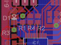
    Access problem ??? Or rather with soldering? In every store they have SMD, and in some (also on Allegro) they sell whole sets, e.g. a set of E12 series resistors from 1R to 1M. I once bought such a set of resistors and capacitors, and I never complain about "availability". And as for the assembly - it is EASIER than through-hole! At least because you do not need to drill holes and turn the plates to solder the element.
  • #58 9625339
    piotrva
    VIP Meritorious for electroda.pl
    leonow32 wrote:
    Access problem ??? Or rather with soldering? In every store they have SMD, and in some (also on Allegro) they sell whole sets, e.g. a set of E12 series resistors from 1R to 1M. I once bought such a set of resistors and capacitors, and I never complain about "availability". And as for the assembly - it is EASIER than through-hole! At least because you do not need to drill holes and turn the plates to solder the element.

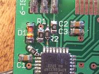
    It all depends on experience, because if someone has both left hands, sometimes SMD assembly can be a torment for soldering and soldered elements :D
  • #59 9627107
    manekinen
    Level 29  
    The first update will probably be tomorrow. So far, there are a few bugs in the program and I'm slowly eating them up with a colleague mlassota we eliminate. It's great if someone else tried to make a tile on their own and helped to test, you know that 3 heads are not 2 ;)

    For now, upgrade the board from 1.0 to 1.1 - as you can see it is simple, just cut two paths and solder two resistors that will limit the current of the ports in the case I described in the previous post:
    uProg - small, fast, portable AVR programmer with SD uProg - small, fast, portable AVR programmer with SD
  • #60 9630316
    krzysiekdg
    Level 13  
    Today I launched this system and I will say that I am very impressed, but on my part I have detected a few shortcomings, namely when we enter any functions, be it flash or eeprom, and so if it goes down to the bottom and one below it seems to have nothing and yet in flash there is probably an invisible CLEAR option, in the eeprom there is also CLEAR, in fusebits it is almost good, but when we go down to the bottom and one below, the highlighting of the inscription disappears, and here also a strange effect because as soon as the highlighting of the inscription disappears and you want to to go back it leaves the option, but the image becomes like a negative, inverted colors only after pressing some arrows up or down everything returns to normal.
    So much for the tests, personally, it does not bother me, but there was a question to test and share comments, so I did :D

    In my layout, I also added backlighting, a nice thing to do in the dark, although I do not think that someone soldered in the dark and programmed something at the same time.
    I could use a battery meter.

    I have not yet modified how this system is programmed by other systems.

    Added after 42 [minutes]:


Topic summary

The discussion revolves around the uProg, a compact and portable AVR programmer that utilizes SD cards for firmware storage. Users express admiration for its design and functionality, highlighting its small size (44 x 39 x 5.5 mm) and fast programming speeds (write: 12.5kB/s, read: 14.5kB/s). Several users inquire about compatibility with various components, such as different LCD displays (notably the Nokia 3310's LPH7779), and the ability to program various AVR microcontrollers, including the ATmega328P and ATtiny series. Issues with SD card compatibility, particularly with SDHC cards, are frequently mentioned, as well as problems related to fusebit settings and display contrast. Suggestions for improvements include adding a battery charging system, enhancing the user interface, and providing better documentation for setup and troubleshooting. The community shares experiences with different configurations, troubleshooting tips, and modifications to enhance the programmer's capabilities.
Summary generated by the language model.
ADVERTISEMENT