logo elektroda
logo elektroda
X
logo elektroda

uProg - small, fast, portable AVR programmer with SD

manekinen 154831 364
ADVERTISEMENT
Treść została przetłumaczona polish » english Zobacz oryginalną wersję tematu
  • #151 9742325
    piotrva
    VIP Meritorious for electroda.pl
    Well rushing. As for the frequency meter, I was thinking about something simple based on AVR - a total of 1 or 2 timers in the prock and we already have a fairly decent meter. One timer counts the impulses from the external timing, the second one measures the time and the meter is ready. But time for software as a medicine.
  • ADVERTISEMENT
  • #152 9748768
    manekinen
    Level 29  
    There is a bug in the Polish version of the license, it says that the English version should be placed in the "system" folder on the card - but as the description, the content of the English license and the location of the license in the update package indicate - it should be in the root directory. Such a small oversight.

    Please also do not pay attention to any errors or typos, it has only one function - it is to make copying and selling the programmer difficult. Its content is secured by calculating the checksum in a very simple but specific way, because as someone wise once wrote:
    Quote:
    The best security is one that nobody knows about


    BUT if someone feels up to it and manages to break this security, i.e. he will manage to remove the license or change its content so that the device looks commercial, and at the same time make the device fully functional - I invite you to PW. Award: 1000 points from me. I am of the opinion that if someone manages to do it for stupid points, then someone else will do it for real money - there is no shortage of frauds and thieves.

    Regards :)
  • ADVERTISEMENT
  • #153 9749382
    tatwo
    Level 11  
    And I have such a question: Will it be possible to use this programmer to somehow program FUNCART or PIC cards.
  • #154 9749444
    piotrva
    VIP Meritorious for electroda.pl
    @ easy - this is a programmer for the Atmel AVR family (in XMega AVR plans) and only these controllers (and not all - see the description, e.g. the new 6-pin attiny4 / 5/9/10) can be programmed with it.
  • #155 9749506
    tatwo
    Level 11  
    Ok only in FunCards is AT90s8515 and 24c serial memory ...
  • ADVERTISEMENT
  • #156 9749565
    piotrva
    VIP Meritorious for electroda.pl
    The AT90S8515 processor is supported by uProga. Serial memories are a completely different matter and uProg has nothing to do with them ;-)
  • #157 9749610
    tatwo
    Level 11  
    Yes, only the memory in the card can be programmed via a loader loaded in the AT, this is how FunCard is programmed in plastic.

    Imagine that you are mounting an old card slot, inserting a FunCard with a DIP-8 slot, in the AT you have a loader loaded and thus you have the possibility of programming and reading the 24c memory.

    Or maybe different. Why do I need a card slot, a card, etc. to load the Dip-8 socket into the programmer?

    About the potential of memory support 24c. I don't have to write such a programmer, especially on the RTV website.
  • #158 9749915
    piotrva
    VIP Meritorious for electroda.pl
    Well, as far as I know, the Author's priorities will be the automation option and the XMega family support. And flash memory in good 328p as a medicine ...
    But maybe, maybe ...
  • ADVERTISEMENT
  • #159 9750140
    tatwo
    Level 11  
    Of course, 24c memories ... are often used both in structures and in RTV equipment, and how many batches can be accommodated on an SD card. Such a programmer would be perfect for repairs
  • #160 9750902
    Simon79
    Level 21  
    Very nice programmer, it is surprising that the author provides the batch for free.
    If someone had a problem with the card (SD ERROR inscription), apart from the capacitor next to it, the main reason is the card, not the programmer.
    The "no name" card, which was added for free to devices and did not have the SDHC inscription and was formatted in FAT32 in the programmer, did not want to work. Another card, branded 2GB, works fine.
    I recommend uProga to everyone! :D
  • #161 9755165
    tatwo
    Level 11  
    Asking the author what do you think and is it feasible?
  • #162 9756149
    danielpoland
    Level 13  
    Hello.

    It is possible, I once made such a programmer for the 24CXX to a friend who has an RTV service.
    Reads and programs all 24CXX memories, the batches are stored on microSD.

    Regards.
  • #163 9756331
    manekinen
    Level 29  
    Simon79 wrote:
    The "no name" card, which was added for free to devices and did not have the SDHC inscription and was formatted in FAT32 in the programmer, did not want to work. Another card, branded 2GB, works fine.

    It's great that you managed to get it started, maybe this card wanted a lot more power and didn't start for that. Perhaps it was some kind of invention / fake.

    tatwo wrote:
    Asking the author what do you think and is it feasible?

    Possible possible, but I do not foresee such functions anymore.

    Added after 23 [minutes]:

    Still on the capacitor for the card. In several sources I asked about 33uF or 22uF capacitors in cabinets up to 1.6mm high - you can't get it anywhere. But you can easily get tantalum capacitors in "A" cases with a capacity of 10uF, they are 1.6mm high, we solder two pieces to the pads of the C4 capacitor and the card works fine. Ceramic capacitors also work well - the dimensions and capacity are the same, you can also buy them without any problems.
  • #164 9772373
    Sebastian.R
    Level 20  
    One suggestion :) Display contacts. there you can use a conductive eraser from another broken display.
    uProg - small, fast, portable AVR programmer with SD
  • #165 9772534
    manekinen
    Level 29  
    The rubber band is problematic because it moves easily and disconnects. When buying or picking out the display, we usually already have either an eraser or a badge. The problem is fixing the display :) But soon (I hope) I will show a custom-made housing for uProg, I do not want to write anything more so as not to confuse, but if it goes well, I will have a lot of them and at a good price - I think that with such a housing the programmer will really look like a programmer real :)
  • #166 9773466
    MatygaD
    Level 15  
    Hello

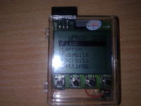
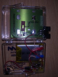
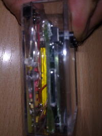
    I made a uProg on a PCB from the author, but I decided to put it in a housing :)
    There was a Maxim sample box lying in the cupboard and I think they were making those boxes under the uProga :)
    Look at the photos for how it fits :)
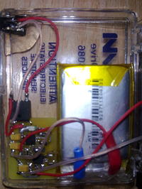
    Since the batteries always run out as needed, I decided to equip the programmer with battery power.
    I had some Li-poly batteries from Philips MP3 players, 3.7V 500mA and decided to use it.
    Charging from a Nokia charger via the Li-Pol MCP73113 controller and the MCP1252-33 × 50 as a 3.3V 120mA power supply.
    Current consumption from the battery when on, about 9 mA, in standby mode 75uA.
    Pytka and Eagle diagram for download.
    Due to the fact that the Nokia charger can give over 7V without load and the MCP73113 has an OVP of 6.2V between the socket and the module, I added a 78M05 stabilizer which is not included in the diagram and board.
    Manekinen again, thanks for the great project and sharing it.

    Regards
    Darek

    uProg - small, fast, portable AVR programmer with SD uProg - small, fast, portable AVR programmer with SD uProg - small, fast, portable AVR programmer with SD uProg - small, fast, portable AVR programmer with SD
  • #167 9774726
    manekinen
    Level 29  
    Thanks to Darek for sticking the photos, it turned out really nice. So you can do something out of nothing, you have to think a little ;) I also have such housings on the desk, in one I have a programmer, in others I keep parts - but it never occurred to me to try on the uProga board for them :)

    I will probably start with Xmega soon - I already have a test processor and a programmer, the only thing left to do is loading the datasheet and laborious scratching of the PDI code.

    And if there is still some memory space, I will try to add battery charging control. The system has two free ADCs and two slow PWMs - like he shot in the face :) So it will probably not be a problem to add a current measuring resistor and a mosfet and charge this battery using soft technology, without the use of dedicated circuits. If you have any nice virulent materials about it, feel free to send us something :)
  • #168 9775698
    MatygaD
    Level 15  
    Hello

    I do not know if it makes sense to integrate the charging functions in the software, having a specialized Li-Po (sample) controller with dimensions of 3x3 mm, especially since it requires virtually no external elements to work, 1 resistor setting the charging current, and a LED signaling charging Moreover, it has built-in functions to prevent the battery from overcharging, which in the case of Li-Pol is very important. And in this case you need to use a 3.3V converter because the battery has 4.2 in a charged state and 3 V in a discharged state. And for this we have MCP1252-33x50 (also samples) :)
    Generally, these cells are charged with constant current, but only until the voltage reaches 4.2V on the cells, and at this level the charger must stabilize the voltage until the current drops to a small value.
    It seems to me that it would be better to add support for the XMega family (PDI) and maybe we could even stuff the programming automation into the software so that you do not have to select eeprom, flash, fusebit, lockbit files separately when programming the system only if the files have the same name is to load the entire set immediately, or, as in the discussion above, create an additional file on the card with the list of files to be loaded into the layout.
    Another such request, can you put a high state on one of the pins as the programmer is on, I mean to control the LED transistor to illuminate the display, sometimes it would be useful when programming the controller in a place where there is little light.

    Regards
    Darek
  • #169 9775750
    manekinen
    Level 29  
    Darku, you have the pins that power the LCD and the card, if the LEDs are low on power, you can safely connect them to the LCD power pin. If more (above 40mA), add a transistor and that's it :)
  • #171 9777876
    farrix
    Level 17  
    Hello

    According to it would be a good idea for me to add a simple but very useful function - a generator for the processor, which in the case of wrong setting of the clock grounds would be like a glove, anyway, you wrote that you have 2 pwm free, so one can be safely used.
    A good solution in subsequent boards, if they were created, would be to use a pulser from the mouse (or maybe you can buy a small one) and add a button to it, the control in this case would be super pleasant.
    Well, I hope that it would be created on xMedia, in your language it supported the tpi protocol. Then nothing could be practically improved (maybe the LCD from E51)

    I also have a question for you if you can buy mega328 together with the programmer board.
  • #172 9778016
    manekinen
    Level 29  
    farrix wrote:
    According to it would be a good idea for me to add a simple but very useful function - a generator for the processor, which in the case of wrong setting of the clock grounds would be like a glove, anyway, you wrote that you have 2 pwm free, so one can be safely used.

    And I am asking you to read the description :) I know that it is long and probably boring, but everything is described there.
    farrix wrote:
    A good solution in subsequent boards, if they were created, would be to use a pulser from the mouse (or maybe you can buy a small one) and add a button to it, the control in this case would be super pleasant.

    Triumph of form over content.
    farrix wrote:
    Well, I hope that it would be created on xMedia, in your language it supported the tpi protocol. Then nothing could be practically improved (maybe the LCD from E51)

    You are already writing about a professional commercial device, uProg will still be developed towards PDI, but not anymore.
    farrix wrote:
    I also have a question for you if you can buy mega328 together with the programmer board.

    I don't have one. Such questions are rather at PW :)
  • #173 9778793
    Sebastian.R
    Level 20  
    As for mega328, I was looking for both ebay and allegro and ... I bought it for just over PLN 20 so it will not ruin anyone. Are available. Unless it is about what is soldered, and already programmed. Because here you need to have a programmer, e.g. usbasp or usbtiny, to program mege first.
  • #174 9797458
    jajen
    Level 17  
    I have a request, can someone take a screenshot of the fusebit settings from the BurnOmat overlay? I don't want to mess with coffee grounds, and I don't know how to set Ext: 07, high :D 0, low: A2 with this program.
  • #176 9797495
    manekinen
    Level 29  
    Enter these values in the "Fuse Hex Editor" tab - nothing easier :)
  • #177 9815205
    Tomekddd
    Level 23  
    I may have a strange question, but I can't get it, the author and the PCB sent me some SMD components and I can't decipher what it is for nothing, namely two with a strip on the left marked A106, one marked 3300, four unmarked but they look to me for capacitors (small orange ones) and two marked 22R0. Are these items up to version 1 or already newer?

    The second thing is the modification of the PCB to a newer version, in the photos I saw a few SMD components soldered on it, what is it?

    And the last thing that stops me from building is the C5 capacitor, what is it supposed to be?
  • #178 9815274
    piotrva
    VIP Meritorious for electroda.pl
    1. 3300 is a 330 Ohm resistor
    2. 22R0 are 22 Ohm resistors
    3.The small orange ones are 100nF capacitors, if I remember correctly
    4.These A106 are 2 electrolytic capacitors 10uF for parallel soldering as C5 (together they will give a capacity of 20uF sufficient to fire the SD card - note polarity)
    5. the modifications are fully described. it's about cutting 2 paths and adding these 22Ohm resistors on the 2 lines of the programmer to limit the current - read the whole topic or the description on my fellow manekinen
    6.the issue of the C5 capacitor was explained when deciphering the elements, besides it was also about it in the topic and on the website ...
  • #179 9815574
    Sebastian.R
    Level 20  
    One thing I came across was about the tFlash card slot. There are at least two types. This is about what has solder points in front of . Unfortunately, I bought another one - with these points on the back. Now I have to buy a suitable socket.
  • #180 9816624
    manekinen
    Level 29  
    You can also solder this one, figure it out. The paths should match, you will have to lead only one with a wire. You have to look at what you are buying :)

Topic summary

The discussion revolves around the uProg, a compact and portable AVR programmer that utilizes SD cards for firmware storage. Users express admiration for its design and functionality, highlighting its small size (44 x 39 x 5.5 mm) and fast programming speeds (write: 12.5kB/s, read: 14.5kB/s). Several users inquire about compatibility with various components, such as different LCD displays (notably the Nokia 3310's LPH7779), and the ability to program various AVR microcontrollers, including the ATmega328P and ATtiny series. Issues with SD card compatibility, particularly with SDHC cards, are frequently mentioned, as well as problems related to fusebit settings and display contrast. Suggestions for improvements include adding a battery charging system, enhancing the user interface, and providing better documentation for setup and troubleshooting. The community shares experiences with different configurations, troubleshooting tips, and modifications to enhance the programmer's capabilities.
Summary generated by the language model.
ADVERTISEMENT