logo elektroda
logo elektroda
X
logo elektroda

Change of the firmware of the LCR T4 M328 element tester from the elektroda.pl g

TechEkspert 63999 72
ADVERTISEMENT
Treść została przetłumaczona polish » english Zobacz oryginalną wersję tematu
  • ADVERTISEMENT
  • #62 18603265
    TechEkspert
    Editor
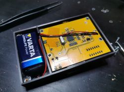
    Looking at the bottom of the PCB these fields are connected in parallel with the SMD quartz resonator, this is probably an option for the through hole version.
  • ADVERTISEMENT
  • #63 18701810
    wujt
    Level 13  
    Hello, in the lcr t4, I beat the display so I wanted to replace it with 2x16 lcd. I have tl866II plus, first I had a problem with programming the atmega328p so I desoldered and replaced it with amega8l, the programmer detects it, unfortunately, after pressing the power button, the bottom row of the display lights up, all segments are lit and it does not respond
  • ADVERTISEMENT
  • #64 18705637
    prosiak_wej
    Level 39  
    TechEkspert wrote:
    Looking at the bottom of the PCB these fields are connected in parallel with the SMD quartz resonator, this is probably an option for the through hole version.


    Exactly. I desoldered the SMD quartz, straightened the legs and soldered in this place, because (most likely today) the tester will stand in the housing and a place for a Li-Poly cell is needed.

    And here's a question for the Ladies and Gentlemen:
    I removed the 78M05 stabilizer, shorted the fields, changed the "upper" voltage measurement resistor to 4.7k (not to scream that the voltage was too low) and through a small step-up converter I power it with Li-Poly. How to modify FW to show battery voltage and turn off at 3.3V? What configuration of divider resistors should I give (I would give higher values so that the current flowing through them was as low as possible)? Of course, I will cut the measuring line from the power supply and connect it directly to the battery.
  • ADVERTISEMENT
  • #65 18937688
    coolers
    Level 11  
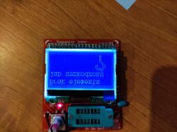
    Hello. Problem a bit strange ... I triggered my m328 because of stupidity, but that's not the problem. I program Atmega, hex, eep and coffee grounds are ok, verification ok, I install and fire, and here zonk ... everything in mirror image ... Help, where is babol ???

    Change of the firmware of the LCR T4 M328 element tester from the elektroda.pl g

    Edyta: The problem is solved, I tested all the available software with the stubbornness of a maniac and found the right one - mega328_wei_st7565_stok.rar from the post https://www.elektroda.pl/rtvforum/topic3402823.html
  • #66 18998142
    wujt
    Level 13  
    Hello, due to the lack of an atmega 328 at hand, I bought a second tester, after three months I did not discharge the capacitor and the tester fell. I ordered an atmega 328 in the 328pb version, I programmed with various batches, the tester fires but does not pass the self test, i.e. after shorting all the terminals, it enters the selftest and so it stays on another software after shorting the terminals, it goes into selftest measures the jumpers as resistors and after some time the inscription not appears calibrate
  • #67 18998156
    piterek-23
    Level 33  
    ATmega328PB is not the same as ATmega328P
  • #68 18998307
    wujt
    Level 13  
    But that it will not be compatible with older versions, they write that it only has more possibilities
  • #69 19132732
    arturroo1234
    Level 12  
    I warmly welcome. And I have a delicate problem, it came to me with a blue button and I put something to test it tests .... It shows the values for 2 seconds and everything disappears when I hold the button pressed it shows the value as long as I hold ... I did the calibration reaches 43% I put a capacitor I will think it crashes End ... And it turns off now when I turn on instead of damaged .... Element, etc. I have 40 pf some capacitor from space on empty pins myfrind sent me with soft soft ... firmware best regards
  • #70 19283405
    maniek1818
    Level 22  
    logos2000 wrote:
    And since the topic about changing the firmware is due to the fact that my original display did not survive the assembly, I decided to adapt a 2x16 display to the existing board (popular HD 47780)
    [...]
    in the firmware attachment


    Why is there no proper symbol defined for resistance in the firmware? Not every display has an Omega. You have to define the symbol yourself. Unfortunately, the author of the modification did not provide his code.
    Ok, I did a batch with Omega.
    mega328_2X...6_menu.zip Download (29.49 kB)Points: 4 for user
  • #71 19793707
    dragolice16
    Level 9  
    arturroo1234 wrote:
    I warmly welcome. And I have a delicate problem, it came to me with a blue button and I put something to test it tests .... It shows the values for 2 seconds and everything disappears when I hold the button pressed it shows the value as long as I hold ... I did the calibration reaches 43% I put a capacitor I will think it crashes End ... And it turns off now when I turn on instead of damaged .... Element, etc. I have 40 pf some capacitor from space on empty pins myfrind sent me with soft soft ... because if so, I will throw something else there best firmware
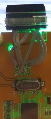
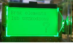
    I had a similar problem after updating the software.
    It turned out that after soldering the wires needed to program the tester, the flux that was in the tin spilled between these pins and caused erroneous readings of the tester.
    Also a good lesson for dirty people - you have to clean up after yourself. :)
    I got a connector and everything works fine:

    Change of the firmware of the LCR T4 M328 element tester from the elektroda.pl g Change of the firmware of the LCR T4 M328 element tester from the elektroda.pl g
  • #72 19893731
    moon09
    Level 15  
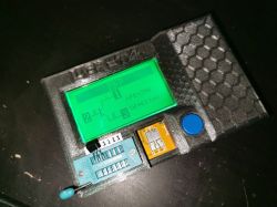
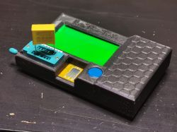
    If anyone would like to, I provide a housing model for the above-mentioned meter by me. A little more compact and according to me more comfortable than the original. Inside there is space for 2.5mm threaded brass inserts. Screw length 10mm. Models (housing and lid) in STL format, packed in a zip. I don't know if it's a good place, but I'm not going to start a whole new DIY topic for that kind of crap. Maybe it will be useful to someone.

    Change of the firmware of the LCR T4 M328 element tester from the elektroda.pl g Change of the firmware of the LCR T4 M328 element tester from the elektroda.pl g Change of the firmware of the LCR T4 M328 element tester from the elektroda.pl g
  • #73 19913420
    pitek3010
    Level 11  
    Hello, I have a problem with the programming of this ATMEGI, I am using the XGecu TL866 II Plus programmer. I am compiling a project in Atmel Studio and I throw hex and eep separately with this programmer, however, after launching the tester, I only see a sequence of random characters on one line on the top and they keep going endlessly. What am I doing wrong?
    In addition, the links to the project changed, it was moved to GIT, the links below:
    https://www.mikrocontroller.net/articles/AVR_Transistortester#Introduction_(English)
    https://github.com/Mikrocontroller-net/transistortester

Topic summary

The discussion revolves around modifying the firmware of the LCR T4 M328 element tester, with users sharing experiences and technical insights on the process. Key points include the availability of source code for the tester, the necessity of calibration after firmware changes, and the challenges faced when attempting to back up original firmware. Users discuss various modifications, including housing changes, power supply adjustments, and display replacements. The conversation also touches on the compatibility of different microcontrollers, the importance of proper programming techniques, and the potential for improved measurement accuracy with updated firmware versions. Several users report successful firmware updates and calibration processes, while others seek assistance with issues related to programming and display functionality.
Summary generated by the language model.
ADVERTISEMENT