logo elektroda
logo elektroda
X
logo elektroda

[BK7321N] How to change the firmware on the LTC LXU407 smart plug with BK7321N chip?

uszatekmis 1047 11
ADVERTISEMENT
Treść została przetłumaczona polish » english Zobacz oryginalną wersję tematu
📢 Listen (AI):
  • Good morning.
    As I've been using a dozen or so smart sockets of one type for over two years, I've finally matured into trying to make them cloud free.
    I use them for Home Assistant with LocalTuya integration (which in itself no longer requires the cloud), but I wanted to change the firmware completely.
    The socket is quite compact (that's what I was looking for), with tuya-cloudcutter it is unfortunately impossible to sflash it (soft 1.1.8).
    But to the edge. It looks like this:
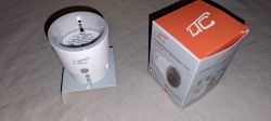
    Smart WiFi socket next to its original packaging on a table. .

    Once I found the right way to open the case it went quite straightforward.
    Under the sticker is a screw with an unusual head (triangular keyway).
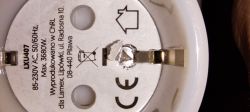
    View of the bottom part of a smart socket with the sticker removed, revealing a triangular screw head. .

    After unscrewing it and gently removing the top, the interior with the stick-on antenna begins to be visible.
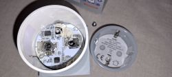
    The image shows the interior of an opened smart plug, revealing the electronic circuit board. .

    You can already find the Beken chip, but I couldn't imagine flashing by touching the chip feet directly (but I was prepared to do so).
    However, after gently peeling off the antenna
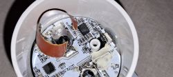
    Interior of a dismantled smart socket showing electronics and a detached antenna.
    and placing the socket upside down with the pins and DELICIOUSLY treating them with a hammer, everything comes out nicely.
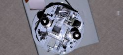
    Image of the interior of a dismantled smart socket with visible electronic components. .

    It remains to be seen what this has on board - BK7231N and BL0942.
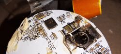
    Close-up of a circuit board featuring a Beken BK7231N chip and other electronic components. .

    The best hides on the opposite side of the board where the chip is.
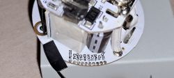
    Inside of a disassembled smart plug showing a circuit board.

    This is where simple flashing remains. It is possible to solder, but I, due to the large number of devices to be reworked, went for spring-loaded pins (pogo-pin) type P50-B1, available on a large Polish shopping portal.
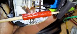
    Interior of a smart socket with connected pogo pins. .

    Pin configuration:
    pin 6 - LED_n 1 / WifiLED_n
    pin 9 - Btn 1
    pin 26 - Rel 1

    Startup script:
    backlog PowerSave 1; startDriver B0942

    I still use

    alias mode_wifi setPinRole 6 WifiLED_n
    alias mode_relay backlog setPinRole 6 LED_n; SetPinChannel 6 1;
    mode_wifi
    addChangeHandler WiFiState == 4 mode_wifi
    addChangeHandler WiFiState != 4 mode_relay

    I noticed that the voltage indication is not very accurate (usually overestimated), so calibration is rather advisable.

    Cool? Ranking DIY
    About Author
    uszatekmis
    Level 11  
    Offline 
    uszatekmis wrote 22 posts with rating 2. Live in city Rzeszów. Been with us since 2007 year.
  • ADVERTISEMENT
  • #2 21474910
    p.kaczmarek2
    Moderator Smart Home
    Do you perhaps have backups of the socket charge? We are collecting them for analysis.

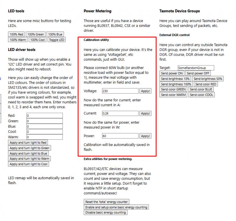
    Calibration is always a must, this can be done via WebApp:
    Calibration panel for devices in Tasmota software. .

    And yes I see you have a new version of this:
    [ESP8266+BL0937] Old Neo Power Plug 16A, 2018, Tasmota, difficult to access pads .
    It resembles this socket, but I couldn't get the plate out of it:
    Socket plug with energy measurement NAS-WR01W and NAS-WR07W [BK7231/BL0937/BL0942] .
    And now I don't know if I missed something then, or if my model was glued and yours wasn't....

    Here someone else was showing a similar copy:
    (BK7231N, BL0942) Opening and changing Nedis WIFIP110FWT firmware (BK7231N, BL0942) .
    So much so that he in turn used a carpenter's squeeze....

    So probably some series are tighter and others weaker glued. I had the same thing with the LSPA9. Some were glued up to the amen and others could be opened with a bare hand.
    Helpful post? Buy me a coffee.
  • ADVERTISEMENT
  • #3 21474942
    uszatekmis
    Level 11  
    >>21474910 .
    Hi.

    Yes, of course I have a copy of the batch, in fact I still have about 12 such slots not converted. I will send on pw (?).
    As for calibration, of course - I know how to do it, I've already done it with other switches (already described so I didn't want to repeat myself) - it's mega easy and very well described. I'm waiting for some larger batch after reworking to do it in bulk.

    I have gone through the topics with the clamps (when looking for a way to disassemble) but using the ChatGPT only directed me to a possible screw under the sticker. The first socket when trying to disassemble survived a little more than the next :-) Incidentally it is made of very robust plastic, you can bend it really hard and nothing. In my case nothing was glued and the whole thing on one, unusual (triangle) screw.
    Searching by name/chip/photos unfortunately yielded nothing.

    I am looking at your post about the NAS-WR07W and it seems to me that the method with a hammer would also work here - in my case there are identical pin mounts in the plastic - it would be done without cutting the case. It's a matter of gently knocking the bases of the pins (those metal stars) out of the plastic they are embedded in. SlawekSS also writes about this in post #4.
  • #4 21476696
    p.kaczmarek2
    Moderator Smart Home
    If searching by name/chip/manufacturer does not work, or more specifically if something is missing from our list:
    https://openbekeniot.github.io/webapp/devicesList.html
    Then please report to me, or even better, give corrections yourself, the source list is available here:
    https://github.com/OpenBekenIOT/webapp/blob/gh-pages/devices.json

    I would also like to add your topic to it, could you paste the full OBK template here in JSON format, preferably with the links to the topic (this one) from the forum already filled in and a link to the photo?


    As for the Tuya memory dumps, we're interested in unpaired ones, as we don't want to accidentally leak someone's SSID. We are collecting them here: https://github.com/openshwprojects/FlashDumps
    Helpful post? Buy me a coffee.
  • ADVERTISEMENT
  • #5 21477124
    uszatekmis
    Level 11  
    p.kaczmarek2 wrote:
    If searching by name/chip/manufacturer does not work, or more specifically if something is missing from our list:
    https://openbekeniot.github.io/webapp/devicesList.html
    Then please report to me, or even better, give corrections yourself, the source list is available here:
    https://github.com/OpenBekenIOT/webapp/blob/gh-pages/devices.json

    I would also like to add your topic to it, could you paste here the full OBK template in JSON format, preferably with already filled in links to the topic (this one) from the forum and a link to the photo?
    .
    I am already correcting myself - template attached.

    p.kaczmarek2 wrote:
    What about Tuya memory dumps, we're interested in unpaired ones, as we don't want to accidentally leak someone's SSID. We collect them here: https://github.com/openshwprojects/FlashDumps
    .
    Here I also accept criticism :-) I made a new dump on the test AP - it does not contain sensitive data.
  • #6 21478189
    p.kaczmarek2
    Moderator Smart Home
    Thanks for sharing the batch (for publication with the test SSID), it is now here:
    https://github.com/openshwprojects/FlashDumps/commit/b9c617c581f88e5ad4f883716009c67a473addd1

    Config Tuya:
    Code: JSON
    Log in, to see the code
    .
    Your template:
    Code: JSON
    Log in, to see the code
    .
    Added:
    https://github.com/OpenBekenIOT/webapp/commit/184f36db7b4be86394fffdfe130a45937c6b4c10
    You should immediately be able to search for this device here:
    https://openbekeniot.github.io/webapp/devicesList.html


    By the way, where did you buy them? I saw the LXU series on our Polish auction portal.
    Screenshot of the device list in the OpenBeken web application. .
    Helpful post? Buy me a coffee.
  • ADVERTISEMENT
  • #7 21478277
    uszatekmis
    Level 11  
    >>21478189 .
    I bought all of them on our Polish auction portal. I think they were even from the same seller. Over an extended interval (roughly over the course of 1.5 years)
  • #8 21478412
    p.kaczmarek2
    Moderator Smart Home
    I have yet to test such products from them:
    RF remote controlled relay socket - LXU200 - short test, interior... .
    Simple timer LXU09 - instructions, interior, cell from inside (holding)

    But better to return to the subject of the socket - and so I would ask, have you seen this feature?
    Charts in OpenBeken - configurable measurement history hosted on an IoT device .
    At my place it is fired up on such sockets.
    Helpful post? Buy me a coffee.
  • #9 21478988
    uszatekmis
    Level 11  
    p.kaczmarek2 wrote:
    .
    But it's better to return to the subject of the nest - and so I'll ask, have you seen this feature?
    Charts in OpenBeken - configurable measurement history hosted on an IoT device .
    At my place it is fired up on such sockets.


    I have read that there is something like this. But in my case, due to the large number of different types of sensors (in total it will add up to more than 50 of various types - temperature, humidity, power, voltage, brightness, opening etc etc) I went into aggregating the results on the Home Asisstant side. And if I want partial results, that's not a problem either.
  • #10 21479006
    p.kaczmarek2
    Moderator Smart Home
    And you will have these 50 devices connected via WiFi?

    After changing the firmware, you can also always connect an additional sensor to any device on free pins. It is only worth ensuring that the method of connection makes sense (measuring the temperature outside and not inside the case, for example).
    Helpful post? Buy me a coffee.
  • #11 21479012
    uszatekmis
    Level 11  
    p.kaczmarek2 wrote:
    And these 50 devices you will have connected via WiFi?
    .

    I will not "be" but "have" connected.
    Not all at once of course, as some are battery operated devices most of their lives "sleeping" but waking up at events.
    I have quite an extensive home network infrastructure, several switches, several APs, several wireless networks, UPS. Somehow it's taken on a life of its own over two years. And I still integrate new things and have new ideas. Such a hobby ;-) .

    Added after 9 minutes:

    But I also have a question about the socket being the subject.
    I want to add functionality to temporarily switch off the LEDs (so they don't light up at night).
    Currently I also use switching the role of the LED depending on the state of the mains connection. Maybe I will paste a piece of code.

    backlog startDriver BL0942; startDriver NTP; PowerSave 1;
    alias mode_none backlog setPinRole 6 LED_n; setPinChannel 6 0;
    alias mode_wifi setPinRole 6 WifiLED_n
    alias mode_relay backlog setPinRole 6 LED_n; setPinChannel 6 1;
    
    ntp_setServer TUTAJ_ADRES_SERWERA_NTP_W_LAN
    ntp_timeZoneOfs 1
    mode_wifi
    
    addChangeHandler WiFiState == 4 mode_relay 
    addChangeHandler WiFiState != 4 mode_wifi
    addClockEvent 22:00:00 0xFF 234 mode_none
    addClockEvent 06:00:00 0xFF 123 mode_relay
    
    .

    In theory this should work - at 22:00 switch the LED off and at 6:00 set it to Channel 1 (i.e. Rel status). Channel 0 is always 0.
    It should - but it doesn't work. If I force Channel 0 to change manually, then the LED state changes.
    Do I then need to add SetChannel 0 0 in mode_none ?

    Added after some time: .

    I have dealt with. Actually you have to add this SetChannel but also to make the diode light up according to the relay status when returning to relay mode you also have to take care of that.

    
    alias mode_none backlog setPinRole 6 LED_n; setPinChannel 6 0; SetChannel 0 0
    alias mode_wifi setPinRole 6 WifiLED_n
    alias mode_relay backlog setPinRole 6 LED_n; setChannel 0 !$Channel1; setPinChannel 6 1
    
  • #12 21480625
    p.kaczmarek2
    Moderator Smart Home
    I didn't have time to write back, but overall you're right, there is a tiny bug - setPinChannel doesn't set the channel value. I'll try to add a test and fix the handling of this situation.

    I only see one bug:
    
    setChannel 0 !$Channel1;
    
    .
    As it is:
    
    setChannel 0 !$CH1;
    
    .


    And soon it will be possible to script in Berry too.
    Helpful post? Buy me a coffee.
📢 Listen (AI):

Topic summary

The discussion focuses on changing the firmware of the LTC LXU407 smart plug, which uses the BK7231N chip, to enable cloud-free operation with Home Assistant via LocalTuya integration. The device is compact and features a unique triangular screw for opening the case, revealing a Beken chip inside. Attempts to flash the firmware with tuya-cloudcutter (soft 1.1.8) were unsuccessful. Contributors share experiences with similar devices, noting variations in assembly such as glued versus screwed cases. Firmware dumps without sensitive data were shared and added to open repositories for analysis and development. The device configuration includes power monitoring and uses the BL0942 energy measurement chip. Discussions also cover calibration procedures via a WebApp, scripting for LED control to disable indicators at night, and potential firmware bugs related to pin channel settings. The conversation references related devices and firmware projects, including OpenBeken and FlashDumps repositories, and highlights the possibility of adding sensors and using IoT-hosted measurement history charts. The user maintains a large home network with multiple sensor types integrated into Home Assistant.
Summary generated by the language model.
ADVERTISEMENT