logo elektroda
logo elektroda
X
logo elektroda

DIY Weller WMRP and WMRT soldering station

hacker_ice 19971 35
ADVERTISEMENT
Treść została przetłumaczona polish » english Zobacz oryginalną wersję tematu
  • #31 19003848
    hacker_ice

    Level 24  
    I have displays and entire boards, soldered and programmed :)
  • ADVERTISEMENT
  • #32 19004269
    Asedio
    Level 13  
    Eh... I've already ordered almost everything :(

    Added after 8 [hours] 5 [minutes]:

    It's been over 1.5 years since your last entry, so I didn't expect you had anything else in stock.
    I ordered the display and the rest along with the tips from RS-Components.
    This is a very interesting topic and I'm surprised it's so little popular.
    It turned out that Dirty rejected it because the size didn't match. I wrote to you privately.
    You didn't respond, so I ordered a PCB from PCBWAY version 1.1, which has programming pins/pins.
    They are already in Poland, I will receive them any day now.
    I got :)
    Updated for today..
    I've got it ready. It works and it seems to be OK, but if the mini-drive socket is bad, the contacts are weak or something else, I don't know, you will burn the tip. This happened to me twice. I managed to save the third one. Everything works, heats and regulates nicely, temperatures are consistent. I have a KTY82 in my stock and everything else. Today I was soldering for an hour, everything was fine, until at some point the display started going blank and the tip started turning red. I took it out in time. I know, it's my fault because I used an arbitrary socket (in a hurry), but in my opinion the design should provide for all possible options that may occur when inserting, removing or even damaging the mini jack socket.
  • ADVERTISEMENT
  • #33 19038709
    Asedio
    Level 13  
    I ordered new branded 3.5mm sockets with thread. Additionally, I will mill the bushings from aluminum PA9 (I have a CNC). I will screw a 3.5mm socket from the bottom. A tip will be inserted into the hole of this 9mm sleeve, so that it will be stiffened on the entire outer metal surface and not only on the 3.5 socket. There will be no forces acting on the plug and socket resulting from pressing the tip during soldering. I will also add that there is newer firmware 9.1 on the author's website.
  • ADVERTISEMENT
  • #34 21051627
    legwion
    Level 2  
    Hello everyone,

    I'm new to this forum and to the world of PIC. I have only made a few small programs using MPLAB X and XC8.
    My problem: I got a new WMRP and I made the subject board. When I connect the WMRP to the PCB it is not recognised: "nc" on the display. However, it heats up non-stop (I limit the current for tests by using a laboratory power supply).
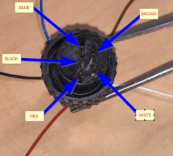
    Strangely enough, my connector doesn't match, but multimeter measurements have enabled me to validate the layout.
    Here's what I found:

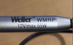
    Weller WMRP soldering iron tip labeled 12V/max. 55W

    Close-up of a connector with five pins and attached wires of different colors: blue, brown, black, red, and white.

    Table showing resistance values and functions for different wire color combinations.

    So it looks like there are different pin-outs?

    I've also noticed that at the TP1 test point I'm not getting the 2.048V I was expecting but 0.75V.

    Can you help me understand why the tool is not detected and why the reference voltage is not present because the programme is a complex one for me, especially as I don't know the CCS environment at all.

    The +5 at the output of the regulator is OK, the components come from RS or FARNELL (no Chinese fakes), PCB manufactured by JLCPCB.

    I have an oscilloscope.

    Thanks for your help.
  • ADVERTISEMENT
  • #35 21053257
    legwion
    Level 2  
    I've found the problem, the system works :)
  • #36 21326007
    warmemberkill
    Level 1  
    >>21053257
    Hello, I have the same problem as you at my station, the VREF (TP1) voltage is not right and my tip is glowing red, can you please tell me how you solved the problem

Topic summary

A DIY soldering station compatible with Weller WMRP and WMRT handles was developed using a PIC16F1788 microcontroller, controlling temperature via a single Alps EC12E2424407 rotary encoder and displaying data on a Lite-On LTC-4627JR or Youngsun ATA3492BR-1 display. The station supports original Weller tips with 3.5mm jack connections, enabling fast heating and features such as PTC thermocouple cold junction compensation, flask presence detection via a magnetic sensor, temperature setback, standby modes, offset adjustments, and selectable temperature units (°C/°F). The design samples plug presence to prevent short circuits during tip insertion/removal. Thermotweezers (WMRT) require original holders connected to standard sockets, while WMRP tips use the mini jack socket without original handles. Temperature stability tests showed a typical 9°C difference between station reading and external thermocouple, with oscillations of 1-2°C. Calibration adjustments were made using multi-turn potentiometers in the amplifier feedback loop. The station uses D-type thermocouples, with firmware updates available (version 9.1). Mechanical improvements include using threaded 3.5mm sockets with aluminum bushings for better tip stability. Community members shared resources such as pinout modifications, thermocouple voltage tables, and 3D printable handle designs. Some users reported issues with tip recognition ("NC" message) and incorrect reference voltage (VREF), which were resolved by verifying connector pinouts and system calibration. The project emphasizes compatibility with Weller components while offering cost-effective alternatives and modular design for soldering and thermotweezers applications.
Summary generated by the language model.
ADVERTISEMENT