Elektroda.com
Elektroda.com
X
This content has been translated flag-pl » flag-en View the original version here.
  • Simple ATmega8 soldering station

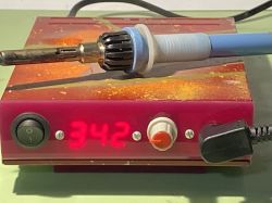
    At some point, I decided that using the same equipment by two people is neither a good nor practical idea. There was a need to make a second soldering station (for my son). The purchase was out of the question for ambitious reasons, I did not want to build something more complicated than the absolute minimum. It was supposed to be small, cheap, working.

    It fell on a project from the Internet.
    https://www.allaboutcircuits.com/projects/do-it-yourself-soldering-station-with-an-atmega8/ by Cezar Chirila.

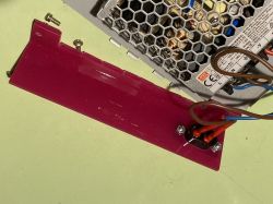
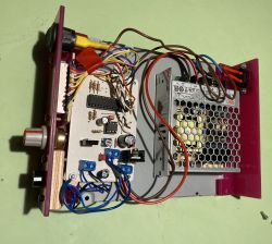
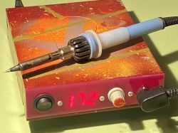
    The station fit in the housing of the CD station, which was lying around the workshop. The front and back plates are L-shaped remnants of plexiglass (the perfect color was chosen), screwed into the housing in the place that used to be occupied by the drive PCB. MeanWell 24V 52W power supply instead of transformer. There is no standby mode - you can add a resistor on the switch (reed switch? miniswitch?) in the WO feedback.

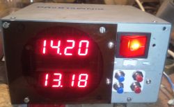
    The temperature indication works as it works, it shows something, one of the board versions has a place for inserting a PR in the amplifier coupling, if someone has something, they can calibrate it.
    Painting with spray varnishes, with the imposition of subsequent strips of masking tape - to somehow mask the appearance of this beggarly casing. The support is made of another piece of plexiglass bent at an angle of 120 degrees.

    Costs: basically the power supply, the rest was in drawers and boxes.
    The stock as you can see - typical, Solomon 24V 48W.

    That's it. My tiles, the rest according to the link. Sufficient for extensive electronics.
    Simple ATmega8 soldering station Simple ATmega8 soldering station Simple ATmega8 soldering station

    In the archive everything that the author of the project has made available, some test .ino in which I do not remember what I checked and pcb.
    Attachments:

    Cool? Ranking DIY
    About Author
    pepepe1
    Level 12  
    Offline 
    pepepe1 wrote 64 posts with rating 114. Been with us since 2003 year.
  • #2
    Fimek
    Level 15  
    Hi,

    There's something about this station :) By the way, memories were revived - 20 years ago I had the same flask operated by a home-made station, but purely analog, with a diode bar-graph on the comparators :) I must admit, however, that Chinese-made miniature soldering stations, type TS100 and similar, as well as those with a T12 tip and "intelligence" in a separate box are simply more convenient to use and among them you can find products with a really good value for money. Nevertheless - a plus for the idea and disposal of "useful" :)

    For my part, I suggest adding some form of a "standby" sensor - for example, based on an accelerometer in the handle, or an optical or magnetic proximity sensor on a stand (such modules are used in 3D printers).

    Regards,
    Fimek
  • #3
    Simon79
    Level 20  
    Interesting and simple design. My soldering iron is starting to malfunction, and although I have already ordered a kit from China to put on a T12 soldering iron, I am tempted to do something like this.
    Earlier, I was thinking about the RL1 soldering iron, also with PID, but this one requires a transformer and my friend writes about the DC power supply in the presented design.
    I understand that the flask with a k-type thermocouple, because it can be different.
  • #4
    maciej_333
    Level 38  
    I will stick to the schematic of this system.
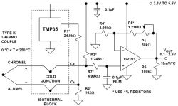
    1. There is a generation sensor in the flask, which is a thermocouple. There is no cold junction compensation. Below is the correct layout:
    Simple ATmega8 soldering station
    source
    The indication of the temperature will therefore be quite random.
    2. C4 is in the wrong place - no low pass filter.
    3. R5 has an invalid value. It should be R5=R4||R6.
    4. Controlling the MOSFET transistor from the microcontroller's output is an error. You can't do it properly without the appropriate driver. The voltage at the output of the microcontroller will still be sufficient to turn it on, but with such control, switching losses will occur.
    5. Controlling the flask heater by PWM is sowing interference. When repairing and constructing various devices, we do not have a casing on, sometimes we take off the screens, etc. A soldering iron lying next to it should not cause additional problems. I would use group regulation here.
  • #5
    -rafal-
    Level 15  
    As soon as you make your own station (I think that it makes sense for a hobbyist, because you can have really good quality soldering at a reasonable cost), I suggest you get interested in the Weller RT/RTM series tips in the future. The handle can be handled on a 3D printer for this source and it's really cool soldering ;) Because this flask from the description is probably for soldering gutters ;)

    Here is an example project:

    http://cairo.us/projects/weller/index.html

    I did it myself and I am very pleased.
  • #6
    pepepe1
    Level 12  
    There is a K thermocouple in the Solomon handle, as in the Weller RT bits. Nothing stands in the way of lowering the power supply to 12 V, setting the appropriate WO gain and using a Weller tip for this station - 150 quills each :) However, I would not make such a station as suggested by my friend -rafal- neither cheaply nor from what I found in the drawers.

    It may be an exaggeration for gutters, but the fact - smd would probably be difficult to solder with it. Which is completely irrelevant, because the user of the smd station does not solder.
  • #7
    podkopiaczeq
    Level 17  
    The power socket needs improvement in my opinion. Neither the power supply nor the tip is grounded.
  • #9
    tmf
    Moderator of Microcontroller designs
    maciej_333 wrote:
    Controlling the MOSFET transistor from the microcontroller output is an error. You can't do it properly without the appropriate driver. The voltage at the output of the microcontroller will still be sufficient to turn it on, but with such control, switching losses will appear.

    That's not true. It all depends on the MOSFET, the switched currents and, above all, the switching frequency.
    For the mentioned IRF540N, VGSth is 2-4V, so ATMega powered from 5V will fully open this transistor. Taking into account the current efficiency of the pin, there is no problem to drive this MOSFET quite efficiently. And you can easily find MOSFETs with better parameters, including MOSFETs with a logic-level gate, which are even designed to be controlled directly from the MCU.
    In this application, currents are poor for this type of transistor, PWM probably does not have a cosmic frequency, so the use of an additional driver would be unjustified extravagance.
  • #10
    satanistik
    Level 27  
    Unfortunately, sometimes when the mosfet falls, the gate is broken and the up output burns. I know that it is not a terrible cost, but sometimes the problem with the batch, e.g. after years.
  • #11
    żarówka rtęciowa
    Level 37  
    Hello

    satanistik wrote:
    Unfortunately, sometimes when the mosfet falls, the gate is broken and the up output burns.


    A properly selected Zener diode connected in parallel to the gate circuit of the MosFet transistor should in total protect the integrated circuit against such damage.
  • #13
    pepepe1
    Level 12  
    I could even buy the whole station ;)
  • #14
    tomiok
    Level 33  
    Way to go.
    I like this initiative very much.
    The more so that somewhere once I had a somewhat similar idea, only lack of time and stubbornness.
    The design was with 3 temperature memories to make it easier.
    Plusik is flying.