If anyone wanted, I can test such a system and adjust it to the required voltage range.
Such powdering of the corpse. New layout and need to be improved. All in all, I've corrected a few different Chinese. Two soldering irons and a USB voltage / current meter. You can have fun in amateur, one-off constructions, but it does not make sense in mass production, even small series.
Cube cool something ala Mini360. Problems can arise with the appropriate choke (self-resonance) and the print run. Otherwise, it will make a nice transmitter.
For me, the bone has only one disadvantage, of course, the price and a small range of supply voltage.
I believe that the diode (SS54) used there causes the internal MOSFET to "burn", especially in the event of its short circuit. Datasheet recommends using a diode with an average forward current of 10A and not only 5A, as in the case of SS54. Of course, I may be wrong ...
In my opinion, the most accurate reasoning. If, as a result, both the diode and the circuit are damaged at the same time, the scenario must proceed in chronological order: the destruction of the diode, then the destruction of the circuit. The reverse scenario is impossible. Looking at the diagram:
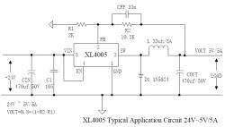
it is clearly visible that no internal short circuit in the XL4005 is able to endanger the diode because for the voltages on the XL4005 the diode is in the reverse direction. Also, the saturation of the choke cannot be the reason for the destruction of the diode, because it only conducts the current coming from the energy of the magnetic field in the choke. So you can even say that saturation protects it in some way, because it limits the power of the impulse induced in the choke after turning off the key in the XL4005.
So the conclusion as to the failure rate of these modules could be made such that the diodes are inadequate to the required parameters and the failure rate of the XL4005 itself is unknown (in fact, it is difficult to require that the XL4005 itself be protected against a diode failure, because it is a catastrophic situation in itself).
Is the USB DVB-T receiver on RTL2832U with alternative software would it be suitable for estimating the level of noise emitted by the converter?
Without a converter, you can't watch from 0, but I recommend this soft to play with: rtlsdr-scanner The subject of efficiency, the level of generated RF disturbances or ripple at the output is very interesting, there remains the measurement methodology, environment and type of load. Unfortunately, I do not have a programmable load with a built-in transient generator and such testing can be key for these converters A colleague of MKPL provided a ready solution to reduce ripple:
"The system also required an additional LC filter at the output. Finally, I changed the capacitors to samyoung NXH (Jamicon TB will also come), then a 15 ~ 25uH choke and a 100uF + 100nF capacitor. The converter started to work cleanly (small ac ripple at the output"
The use of linear stabilizers behind the switch-mode converter is a common practice that also reduces ripple.
If anyone wanted, I can test such a system and adjust it to the required voltage range.
Such powdering of the corpse. New layout and need to be improved. All in all, I've corrected a few different Chinese. Two soldering irons and a USB voltage / current meter. You can have fun in amateur, one-off constructions, but it does not make sense in mass production, even small series.
Cube cool something ala Mini360. Problems can arise with the appropriate choke (self-resonance) and the print run. Otherwise, it will make a nice transmitter.
I found a few designs with this scalak on the net. Unfortunately, there are no opinions about it.
mkpl wrote:
For me, the bone has only one disadvantage, of course, the price and a small range of supply voltage.
The price is not bad if you consider how much it costs, e.g. LM2576 + heat sink. Unfortunately, the input voltage range is a bit small. Maybe I can find another synchronous system with a wider range of input voltages.
The CMS moderator reported to me that he would perform the XL4005 and XL4015 tests again. The XL4005 will even deliberately overload it until it burns. I just handed over the test modules to him. Soon he should publish the result of tests on this topic.
The XL4005 will even deliberately overload it until it burns.
This is the moment I'm waiting for the most .
yogi009 wrote:
And pictures from the oscilloscope, please!
Will do .
I don't know if I can make it this weekend, but the first article will be coming out within a week.
I will reveal the secret and say that apart from the two converters mentioned above, I got a few other "toys" and articles about them will be written successively.
An interesting topic, I am waiting for further tests and an attempt to determine the amount of generated disturbances. If it is not possible to use a spectrum analyzer or to estimate using a scanner on the RTLSDR and a USB DVB-T dongle, maybe it will be possible to estimate the influence on e.g. AM LW / MW and FM radio receivers working in the vicinity?
and wouldn't it be better to organize this electrode forum so that each user of the electrode with an excess of some modules could send a test module to one person from this forum, including destructive tests (overload, overvoltage, high temperature (e.g. the founder of this subject or preferably a person who has an oscilloscope, spectrum analyzer, artificial load, etc. and has an idea how to conduct meaningful tests)? What do you think about such a concept? of course the author of this topic would have to consent to it or another person who has a full set of equipment and knowledge to carry out Such tests would be subjected to various available modules, and the "reward" for the tester, e.g. "free", would be the same module (e.g. for testing it would be necessary to provide at least 2 of a given module)
It would be nice to see such tests of all modules from China: - all available DC / DC converters - Wi-Fi / LoRa / GSM modules (e.g. their maximum transfer capabilities, signal strength, range tests) - analog-to-digital converters (their real accuracy) - BMSs (their actual threshold voltages - voltages at which they respond) - camera module tests (image quality / actual resolution, quality) - modules measuring the flowing current (e.g. ACS712 and its actual accuracy) - GPS modules (measurements of the actual accuracy of measurements, speed, etc.) - gas sensor modules (LPG, CO2 etc.) - tests of microwave sensors (their range in various conditions)
It would be nice to see such tests of all modules from China:
1. Such tests (e.g. in ITR) cost tens of thousands of zlotys (below 10,000 are hard to fit). 2. They should be carried out by the manufacturer 3. What to expect when the entire module costs less than the (good quality) chip for it?
You gave the impression that you read one post in the entire discussion
Maybe so. I wonder what these tests are for? To prove that Chinese gu .... jest gu ....? It is known. All in all, this type of product should say "You use it at your own risk, the manufacturer is not responsible for any damage caused by this ..."
-> @ AnicoZ There are those who will pay 5x as much for "Chinese g ..." wrapped in silver, and will be praised everywhere. 100% of the bitten apples are produced in China ...
In these tests, it is about real determination of parameters because today everyone who is still swimming in this global shit on the surface is cheating, the honest ones have drowned in it a long time ago.
The user of grala1 helps me a lot by testing the electronic modules. As soon as I found out that his converter burned down during the tests, I immediately sent a new one. It turned out that the second was also damaged. I don't know if the heat sink would help, but I suggest avoiding this module if your system is a bit more power hungry. And people buy it in thousands. The gra1 tests are not ordered by the producers, I test them ourselves and we buy the modules ourselves, so we are not afraid to write the truth. Interesting if the interference test fell out after the bands.
If anyone would be interested in similar reviews, have some measuring equipment and a light pen, feel free to do so.
Try to use the RTL-SDR tuner to suspect interference, I use it before visiting the EMC chamber and usually I can prepare myself, i.e. I see what frequencies are spreading and what is responsible for it. Thanks to this, in the chamber itself, I know where to look and what to improve in order to reduce interference.
I'll refresh the topic. Today I was running a ready-made Chinese converter on the XL4005E, replacing the potentiometer with a permanent resistor. To my surprise, the feedback voltage was not 0.8V (as in the catalog note) but 1.25V. Can anyone confirm the voltage on pin 2 ?.
Hello, I used this converter to lower the voltage from 20V to 9.2V in a 27MHz radio-controlled toy, the control range has decreased from several dozen meters to three, screening the module did not help, is there any other simple way to get rid of interference?
Only a linear stabilizer. Since it is a toy control, there is no good radio circuitry, so any interference will catch. You can try to filter out the power supply with the RC circuit, but it may not help much.
Hello, I used this converter to lower the voltage from 20V to 9.2V in a 27MHz radio-controlled toy, the control range has decreased from several dozen meters to three, screening the module did not help, is there any other simple way to get rid of interference?
What electricity is needed? Ready modules for the LM317 / 350 are also there. only can you fit? Because linear modules with the voltage drop you give may require a heat sink. But it can be specified as you specify the requirements. Or Go to the website, even if TME has filters, you can pre-filter according to the required current and select the LDO option, this is a slightly better solution. the stabilizer may or may not be adjustable. But it's a reading on coffee grounds because we don't know what you really need.
I really need a simple way to lower the voltage from the Parkside 20V battery to 9.6V without any interference on the wire, the current is rather small, because the original battery is the NI-MH 9.6V 2200mAh package. The inverter unfortunately disturbs the range despite screening.