logo elektroda
logo elektroda
X
logo elektroda

Hilti C4/36-350 Charger Issue: Green LED Flashing Every 2s, Battery Not Charging

rsv6 106509 223
ADVERTISEMENT
Treść została przetłumaczona polish » english Zobacz oryginalną wersję tematu
  • #121 20759698
    ionel calota
    Level 10  

    MIP2M2 and the three 1R resistors must be replaced.
  • ADVERTISEMENT
  • #122 20760574
    marcocand
    Level 6  

    My model is 230VAC (C 4/36-350).

    The ZD6 Zener diode is 15V, while D15 is a BAS16J SOD-323 diode. Mine is printed (AR).

    Z15?
    Will it be D15 or DZ15? Let me know.

    I have these burnt resistors R24, R30, R33. Are they 1Ω?
    While the resistors R38, R39 have what value?
    Thank you.

    Added after 14 [minutes]:

    If resistor R24, R30, R33 burns out, you may have a short circuit in IC2 MIP2M2 between pins 5 and 7.
  • #123 20760785
    DRAZEK87
    Level 15  
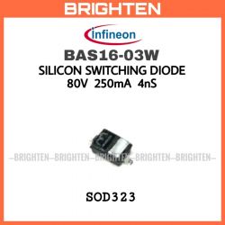
    I have determined the diode D15 is BAS16-03W in the SOD-323 Silicon Switching Diode 80V 250mA 4ns housing and labeled as "B", not 13; there are several of them on the board e.g. : near relay RY2 diode D117. Preview photo of the correct diode:
    Image of BAS16-03W diode by Infineon in SOD-323 package.

    Ashenvale wrote:
    ... Now when the 230V~ power supply is connected there is no voltage on C3. I checked the branch that feeds L2 and it seems to me that the problem is on the ZD1 - ZD6 jumpers.
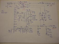
    I'm throwing in a small part of the schematic .... for clarification.
    Hand-drawn electronic schematic with labeled components.


    The above schematic is incorrectly drawn !


    The absence of circuit Q7, and it is BC817DPN labeled as "N4" in SOT457 housing (it is not on the schematic) or its damage causes incorrect control of optocoupler PC1 that is MOC3063, and it in turn affects the operation of triac CF1, and it is: BTA12-600B which partially charges the main grid capacitor C3 hence the above voltages in the schematic shown on Zener diodes ZD1-ZD6 are incorrect.

    marcocand wrote:

    >>20594619 Hi, check carefully because in my case Q5 is a MOSFET type BSS138N with SK𝚜 designation. I am attaching a schematic with Q5 and components connected correctly.
    Hand-drawn schematic of a circuit with electronic components like diodes and transistors.


    This above schematic is better drawn, but an error crept in there because BSS138N is Q10! not Q5 which is BCP54 see my schematics drawn above; moreover, it is heavily truncated and there is no circuit on it: Q7 or CF1 which are key elements to understand the principle of operation of this part of the power supply block which is responsible for the correct operation of IC2 = MIPZM2.

    I present a detailed schematic of this sector which will allow us to repair to get the correct voltage on C3 and run the next sectors that have already been discussed. Most of the components what I measured I have given their correct values and deciphered SMD circuits.... Schematics posted by me for posterity. Good luck with the repair: D give a "+" if I helped.

    Hand-drawn schematic of an electronic circuit with various components. .
  • #124 20762396
    Marko121
    Level 17  
    The diodes according to my measurements are :
    ZD1 to ZD5 = 75V (measurements from 75 to78 v) they are definitely not 15v
    on ZD6 at my place it indicates 13,3V (maybe it is 15V I don't know if it's a scatter or if it is 13v so it would be good for someone to confirm it yet)
    ZD9= 15V
    ZD10=15V
    ZD11=15V
    ZD13 =? (above 160V)
    ZD14=11V
    ZD15=9V
    ZD16=5,1V
    ZD17=17,8V

    I'm posting my piece of schematic with transistor Q7 (you got ahead of me DRAZEK87 in drawing but I'm posting, I didn't compare them so I don't exclude the possibility that I might have made a mistake somewhere ) I updated the schematic because the shorted q10 led to a drawing error
  • ADVERTISEMENT
  • #125 20762534
    DRAZEK87
    Level 15  

    Marko121 wrote:
    Diodes according to my measurements are:
    ZD1 to ZD5 = 75V (measurements from 75 to 78V). They are definitely not 15V.
    On ZD6 at my place, it indicates 13.3V (maybe it is 15V. I don't know if it is spread or it is 13V, so it would be good for someone to confirm it still).
    ZD9 = 15V
    ZD10 = 15V
    ZD11 = 15V
    ZD13 = ? (above 160V)
    ZD14 = 11V
    ZD15 = 9V
    ZD16 = 5.1V
    ZD17 = 17.8V

    I'm posting my piece of schematic with transistor Q7 (you got ahead of me DRAZEK87 in drawing, but I'm posting. I didn't compare them, so I don't exclude that I could have made a mistake somewhere)

    Super that you are together. We will figure out the nut.... we will help others... soon I will have KT4H, then I will measure all diodes carefully.... me waiting for the missing parts.... you did a great job... I myself know how much time it costs.... but someone has to do it because these chargers are breaking too much and supposedly HILTI....
  • #126 20763343
    Marko121
    Level 17  
    DRAZEK87 wrote:
    Super that you are together figuring out the nut .... You did a great job ... I myself know how much time it costs ....
    Thanks and to each other . If I didn't see such commitment and willingness to share in this topic I wouldn't get involved :) .
  • #127 20763686
    marcocand
    Level 6  
    >>20746882
    You're right, it's Q10, I've attached the modified diagram. Hand-drawn schematic of an electronic circuit with labeled components such as resistors, diodes, and a transistor.

    Added after 2 [hours] 12 [minutes]:

    If you are interested, the diodes I listed below were removed from the circuit and measured.
    ZD6 =15V
    ZD9= 15V
    ZD10=15V
    ZD11=15V
    ZD14=11V
    ZD15=11V
    ZD16=5.1V
    ZD17=15V
    Where is ZD13 located?
  • #128 20764662
    Marko121
    Level 17  
    here zd13 marked


    Electrical schematic with marked ZD13 diode.


    Printed circuit board with marked faulty components.

    there is another diode without marking in print not sure what kind . To me it is a 6V8 zener. As you can confirm it

    I don't really understand the operation of the circuit with transistor Q7 . is there something generated there?
  • #129 20765931
    DRAZEK87
    Level 15  
    Marko121 wrote:

    I don't really understand how the system with the Q7 transistor works. Is anything being generated there?


    This whole triac system, in my opinion, is a protection against too high and too low voltage on C3. The ladder of zener diodes ZD1-ZD6 sets the operating threshold of transistor Q10. If the voltage is too high, the transistor will block the diode in PC1, and this will block the triac. Q7 is responsible for controlling PC1 to properly charge C3. It is possible that it also plays the role of selecting the voltage in the 110/230V network, but I have not determined this. He may also be responsible for a soft start. Let others comment. In any case, the lack of Q7 or its damage causes incorrect operation of the triac, and the voltage on C3 fluctuates around 200V, which is too little. When I receive Q7, I will write to you exactly what the voltages should be on individual Zener diodes and everything else in the area.
  • ADVERTISEMENT
  • #130 20778029
    DRAZEK87
    Level 15  
    Update... I am already in possession of a KT4H meter and took measurements of the Zener diodes from ZD1 to ZD6 and as it turned out they are consistent with the statement:

    Marko121 wrote:
    the diodes according to my measurements are :
    ZD1 to ZD5 = 75V (measurements from 75 to78 v) they are definitely not 15v
    on ZD6 at me it indicates 13.3V (maybe it is 15V I don't know if it is a spread or if it is 13v so it would be good for someone to confirm it still)
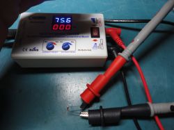
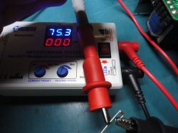
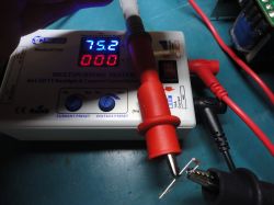
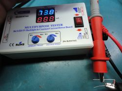
    see photo diode ZD1:


    KT4H multimeter displaying 75.6 V with test leads connected to a component.

    ZD2:


    Multimeter KT4H measuring diodes

    ZD3:


    Multifunction tester KT4H with probe wires and a component.

    ZD4:


    KT4H multipurpose tester with dual displays showing voltage and current.

    ZD5:


    KT4H tester with a display showing the measurement result.

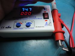
    after measuring ZD6, it is obvious that it is defective; it is erroneously measured because in both directions, and the meter presented it like this:

    KT4H universal tester for measuring constant currents and Zener diodes.


    on a quick note I substituted 5.1v there but it doesn't change anything now I'll give the right 15v and see what happens next;
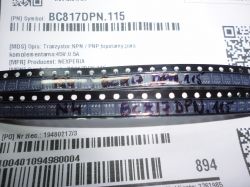
    except I'm already in possession of a BAS16-03W diode, a MIP2M2 controller and a BC817DPN transistor which actually has "N4" printed on it and looks like this:

    Two strips with transistors marked BC817DPN.115, lying on a label with a barcode and description.

    I will soon proceed to replace the damaged components and report back :D

    Added after 4 [hours] 50 [minutes]:

    Marko121 wrote:
    Here zd13 marked

    Electrical schematic with marked ZD13 diode.

    Printed circuit board with marked faulty components.


    Here is another diode without marking in print not sure what kind . To me it is a 6V8 zener. As you can confirm it

    I don't really understand the operation of the circuit with transistor Q7 . is there something generated there?


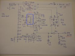
    the unknown diode is a 5.1V Zener diode measured and sure enough 100% has a characteristic blue stripe like other diodes on this board with a blue stripe.... its marking on the schematic not known no printing on the board; this is the diode see photo, I marked in blue:

    Hand-drawn electrical schematic with a highlighted section in blue.

    and as for diode ZD13 good question what is this diode because in my case it is defective and for posterity its missing/burning causes the T2 transformer to squeal, but when we have a working IC2 circuit the green control diode is lit we have 13v on pin 4 of the circuit in question....

    diode ZD13 has EBV Z318 or 58V Z318 marked on it where Z318 is probably the production date it is possible that it is a diode for 58v but I can't determine that because it is burned out, "Marko121" writes that it is above 160v I need to determine that .... I am working on it as I decipher its nominal I will let you know .... for today the charger has already recovered the lost 13v and the diode shines elegantly green greetings

    and finally without a working IC2 will not work properly triac ....

    Added after 11 [minutes]:

    marcocand wrote:
    If you are interested, the diodes I have listed below have been removed from the circuit and measured. ZD6=15V ZD9=15V ZD10=15V ZD11=15V ZD14=11V ZD15=11V ZD16=5.1V ZD17=15V Where is ZD13 located?


    confirm I checked myself, measured :

    ZD11 is 15v
    ZD14 is 11v
    ZD15 is 11v
    ZD17 is 15v
  • #131 20780789
    chipeservice
    Level 1  

    Hi, I have this charger and want to repair it. My main fuse is blowing. When I put a light bulb in series with the fuse, it just blinks at intervals of about 1 second. Can someone explain how the circuit flows through this charger? I have maybe 5-6 pieces and want to repair each one. Thanks.
  • #132 20782403
    Marko121
    Level 17  
    chipeservice wrote:

    Hi, I have this charger and want to fix it. My main fuse is blowing. When I connect the bulb in series with the fuse, it only blinks at intervals of about 1 second. Can anyone explain to me how the circuit flows in this charger? I have maybe 5-6 pieces and I want to fix each one. Thanks


    Such questions? forgive me, but the repair of this charger really already requires some knowledge of electronics and the operation of Inverters In this topic is contained a lot of knowledge (as few where) on the repair, including diagrams drawn from print which requires a lot of time and dedication. Learn to use it.... look for a short in the circuit , It could be anything from the rectifier bridge etc...

    DRAZEK87 wrote:

    unknown diode is a 5.1V Zener diode measured and sure enough 100% has a characteristic blue stripe like other diodes on this board with a blue stripe.... its marking on the schematic not known no printing on the board; this is the diode see photo, I marked in blue:

    in my case, all diodes have the same black bars and yet different values and in my case it is a 6V8 diode because that's what the measurements indicate (unless it's so messed up parameters )

    DRAZEK87 wrote:

    a good question about diode ZD13 what is this diode because in my case it is damaged and for posterity its absence / burnout causes squealing of transformer T2, but when we have a working IC2 circuit we have 13v on pin 4 of the circuit in question the green control diode lights up....

    diode ZD13 has EBV Z318 or 58V Z318 marked on it where Z318 is probably the production date it is possible that it is a diode for 58v but I can't determine that because it is burned out, "Marko121" writes that it is above 160v I need to determine that .... I am working on it as I decipher its nominal I will let you know .... as of today the charger has already recovered the lost 13v and the diode glows elegantly green greetings

    Hmm.... on my board I am not able to read the writing of this diode ZD13 but during operation with the battery inserted on this diode I have 160V DC here measurements may be wrong because there are large frequency pins and this diode together with diode d5 protects IC2 from too high induction pulses from the transformer

    What about my case : I got the ordered transistor Q10 (BSS138N) (marking SKs) I replaced it and the diode lit up nicely green . It looks like the charger will work (although I also bought all the other ICs )

    I'll also add that the voltage on the collector supplying Q5 (BCP54)= 13V but only when there is no battery inserted ( that is in st-by mode) and also on the emitter is then 0.7V, only after inserting the battery on the collector Q5 appears 17.2V and on the emitter is then 14.2V and only then is the circuit JC1 (L6599AD) powered and the fan begins to rotate
  • #133 20782725
    DRAZEK87
    Level 15  

    Marko121 wrote:
    Hmm.... on my board I am not able to read the inscription of this diode ZD13 but during operation with battery inserted on this diode I have 160V DC here measurements may be wrong because there are large frequency pins and this diode together with diode D5 protects IC2 from too high induction pulses from the transformer
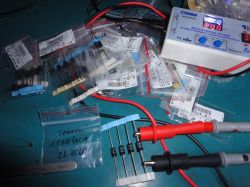

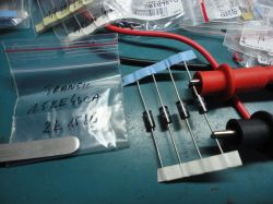
    Diode ZD13 has to "figure out" what it is because I need it and others will in the future... under a microscope it's hard to read its print if it was a diode what is 58V and so fits the print why do you have 160V there unless you measure to another ground or another plus field take the ground from the bridge or C3.... and the best thing would be to take a measurement with this meter what I have but a working diode then we would have 100% answer what is sitting there.... but at the moment I do not have a working copy of this charger.... and when I had one I did not measure it because I did not need to measure this diode.... i.e. I wrote earlier I am not able to check everything but with time we will master this charger in every range .... a matter of time ...

    Diode D5 and ZD13 for me is a resistor and capacitor so-called "gasifier" must beat the pins on the trafnik here direct measurement during operation of the charger can be completely distorted ... try to "Marko121" read the value ... hope in you
  • #134 20782805
    Marko121
    Level 17  
    I can not read it (too smudged or wiped) but the diode d13 is definitely not 58V because I measured with a similar made meter ( what you have the original) but only to 160v and it did not penetrate it so it can not be 58V. Since there is a DC 160V directly on it ( between the anode and cathode ) when the charger is running, maybe it is its zener voltage although it can be much higher. Maybe someone can read these values from his PCB
  • #135 20784149
    DRAZEK87
    Level 15  
    It won't be 58V, I have thoroughly cleaned the diode and it is marked EBV like an ox, and consecutively Z318, but I can't find anything under this code on the web.... Someone measure this diode correctly.... It will come to me to acquire another charger to help myself....
  • #136 20785152
    marcocand
    Level 6  

    Hi everyone, my ZD13 zener diode is marked EUV Z83L and is 220V. When disconnected and measured, it gives me this value.
    The code marking is EUV. Could it be a SMAJ188A-TR?
    STMicroelectronics
  • #137 20785793
    Marko121
    Level 17  
    I found MIP2F20MS1SO applications in a different scheme... it wasn't easy :) I thought that Panasonic produced these MIP2m2 only for Hilti :) There is a similar solution with a combined diode (D602 ST02D-200TA), see the diagram, maybe you can use such a solution if no one can decipher D13, but maybe someone's PCB will mark this element differently than yours, maybe then something can be located because about EBV Z318 actually google says nothing or maybe it is zener 318V?

    and yet another solution with a diode, a resistor and a capacitor
  • #138 20786236
    marcocand
    Level 6  
    The ZD13 diode with EBV marking corresponds to SMAJ188CA-TR
    STMicroelectronics Bidirectional TVS Diode.
  • #139 20786769
    Marko121
    Level 17  
    So, from the SMAJ188A-TR EUV pdf specification it appears that the EUV marking is: (Unidirectional) unidirectional transil 188v and SMAJ188CA-TR mark. EBV is a (Bidirectional) bidirectional 188V transil. Thanks for the info marcocand
  • #140 20788509
    DRAZEK87
    Level 15  

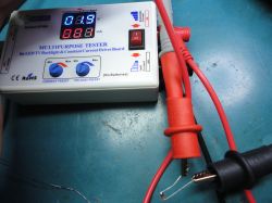
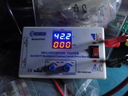
    In fact, the PDF page 10/12 shows that the marking: EBV is a SMAJ188CA-TR transzil diode, i.e. TVS; 400W; 209V; 6A; two-way; SMA and they have it at TME, and I just placed an order there :/ it's a pity because I would have added it to the package because I don't have it in stock; but that's not a bad thing, it turned out that the diode is working!!! and I was confused by the print on the power supply board, because since it's a ZD13 Zener diode, the measurement in one direction should be correct, and I noticed a break in both directions, and it didn't occur to me that there could be a transzil there that would show a break in both directions during the measurement; now we know "for posterity" what's going on there and look, the diode measurement shows the result in the range of 220v +-5v depending on how the meter is set; but before I measured the correct diode for example, I took a 43v transil to be sure that the measurement was correct. A few photos from the measurements.

    1.5KE43CA diode
    Close-up of a workspace with electronic components and a multimeter on a blue workbench.
    Measuring diode with a multifunction tester on a workbench
    Transils on a workbench with measurement probes.
    Multipurpose tester with a display showing 42.2 V and 0 mA.

    ZD13 SMAJ188CA-TR diode, its marking: EBV
    Electronic tester on a table with diodes and measurement cables.

    Inserting the ZD13 diode does not eliminate the squeaking noise on T2 that I wrote about earlier; probably only the assignment of the keys and the IC1 system; i.e. loading the converter will eliminate this phenomenon, but I will write about it later.

    Now we found out who the mysterious ZD13 is. There is strength in the group. On to the next topic.
  • #141 20789901
    DRAZEK87
    Level 15  

    Please measure the C11 capacitor. We have it in the PC3 optocoupler branch or on the side of the IC1 L6599AD system, pin 5 or R25. The capacitor is in housing 0402 and probably for a voltage of up to 25V. When I re-measured the C4 capacitor during another repair, it was measured in the range of 1nF and it will also be for 25V because I have new ones for 50V and they are twice as high. In this charger, both of them are charged. Please verify.
  • #142 20791396
    Marko121
    Level 17  
    In this case, I would suggest the catalog note of the system, i.e. c11 (cat. c44 = 10 nF) and c4 (cat. c43 = 4.7 nF), although it seems to me that the capacitances are not as important as what they are broken for, I think that the IC to exchange
  • ADVERTISEMENT
  • #143 20796093
    DRAZEK87
    Level 15  

    I assume that C11 is 10nF because I have seen this value on the diagrams of other power supplies, but it would be nice if someone checked it. This charger got a real kick, I think that the more there was an attempt to repair it, the more elements were grounded, some of the diodes were soldered incorrectly and the PC3 optocoupler with the symbol V0615A-9 was blown up in the direction and value, which is an interesting thing, I have never encountered a damaged one before element; Ic1 system with basket space; classic with burnt mass; all resistors have been checked and have the correct value, but you can see that several of them have been replaced... and I checked one more thing and confirm the next Zener diodes:

    ZD16 is 5.1V
    ZD9 and ZD10 are 15V
  • #144 20799967
    DRAZEK87
    Level 15  
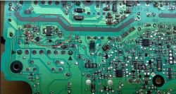
    Topic update. Please try to indicate the value of the PTC1 element, which is a thermistor and is located near the Q4 key, see photo
    Circuit board with marked location of missing PTC1 component.

    In this charger it is missing and was probably accidentally removed when replacing the transistor. In the attached photos in this topic, all boards have PTC1 soldered, but its value is unknown. According to the technical documentation of the L6599AD system, a signal blocking the operation is given to the input of pin 8 of the system, so increasing the temperature on the thermistor near the Q4 key will cause deceleration or complete disconnection/blocking of the system. In addition, I wired the entire unit, checking all resistors and measured capacitors in the system; here are the next values:

    C16 is 100nF;
    C13 is 470nF;
    C8 measures around 4.7uF;
    C6 around 220nF;
    C5 strange measurement 730pF is probably 1nF;
    C14 another strange measurement around 750pF is probably 1nF;
    I tried to measure C7 and it showed 500nF, this is definitely an incorrect measurement, either 470nF or it is damaged because it is near the damaged PC3 and the Q6 transistor, which has already been replaced.

    After replacing the new IC1, but due to the lack of PTC1, when I try to start it, there is silence, even the previous 13v does not start, so I will desolder IC1 again and check if it will change the state to the previous one.
  • #145 20800956
    Marko121
    Level 17  
    PTC1 is most likely a 470 ohm PTC limit thermistor and this is my measured value at room temperature, its value increases rapidly after exceeding the limit temperature, unfortunately I do not know what its limit temperature is. If you know that it is 470 ohms, you can insert a resistor and continue working until you buy a PTC. I think it may be something like this
  • #146 20801282
    DRAZEK87
    Level 15  
    Marko121 wrote:
    PTC1 is most likely a 470 ohm PTC limit thermistor and this is my measured value at room temperature, its value increases rapidly after exceeding the limit temperature, unfortunately I do not know what its limit temperature is. If you know that it has 470 ohms, you can insert a resistor and continue working until you buy a PTC. I think it may be something like this


    Correct ! Today I managed to determine it and I confirm that it is PTC 470R in housing 0603, they are available at TME; and I accessed it in such a way that I had all the damaged elements in the bag and, by pointing them out one by one, I was left with 2 unknown ones, visually similar to capacitors, but they were not capacitors because I could not measure them capacitatively; only when measuring the resistance of the smallest element it measured around 490R, and since it was PTC, I heated it and it started to increase its resistance. Great, another element confirmed and I will also add that we have one more thermistor, NTC101, which is located within the output diodes and its value is 10kR, checked.

    But the most interesting thing in all this is that among the damaged elements there is a mysterious one: TLE4266G which, as I checked, is a 5V stabilizer, and on this charger's board it can only be Q104, where in the photo it is BCP54, the same as Q5:
    Close-up of a circuit board with a highlighted electronic component.
    Was the TLE4266G stabilizer incorrectly substituted for Q5 and burned, or should it be Q104? Check "Marko121" what you have soldered behind Q104 because I know that there are different versions of these chargers and maybe there should actually be a 5v stabilizer there, not a BCP54 transistor.
  • #148 20860262
    PiterSen151
    Level 10  
    Hi. Symptoms: the power diode lights up, after inserting the battery the fan turns on for a few seconds, the battery charging current of about 200 mA appears and the process stops after a few seconds. Batteries, keys in working order. I can't figure out how the PC4 optocoupler is powered (it doesn't drive Q5 for me). It takes ground to one leg from trafo T2 and the other is supplied by series connected resistor R191 1k and capacitor C146 4.7u (both working) to (I think) the second leg of controller Q105 - invisible markings, I can try to read under a microscope if it's important. (I think the power supply in series through this capacitor is out - unless it's a high-pass filter?). In addition, there is some tiny diode D119 (working 0.5V drop) plugged into the legs of PC4 in parallel. On the other side of PC4 I replaced burnt J3 0R and diode D9. The rest of the components seem to be in working order. I didn't solder out PC4 for now because I didn't find voltage on its leg so it may be working. PC3 is powered and works. The diode D104 after the transformer gives 8V. On Q5 I have 12V on the input but the lack of current at the base blocks the operation of the downstream circuits.
  • #149 20869130
    DRAZEK87
    Level 15  
    PiterSen151 wrote:
    I can`t figure out how the PC4 optocoupler is powered (it doesn`t control Q5). It takes ground from the T2 transformer to one pin and the other is connected through a series-connected resistor R191 1k and capacitor C146 4.7u (both functional) to (probably the other) pin of the Q105 controller - invisible markings, I can try to read them under a microscope if it is important. (it seems to me that the power supply in series through this capacitor is out of the question - unless it is a high-pass filter?)
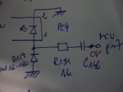
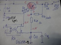
    PC4 optocoupler from the side of the IC105 microcontroller from pin 7, see photo:

    Electronic circuit diagram featuring optocoupler PC4 and related components.

    through a filter, i.e. you mention: C146 and R191 1kR and the D119 BAS16-03W diode powers the diode in PC4 which then, through a transistor, see photo:

    Hand-drawn electrical schematic with labeled components.

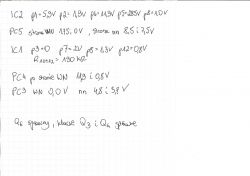
    I will control the Q5 base and pass 13V from the collector to the emitter, and this will then activate IC1. If the processor does not receive all the correct signals, it will not start Q5 and will not power IC1, and it will turn off and the main converter will be in a dead state, which will result in no battery charging. Note that on PC4 pin 4 we have a voltage of 13v (generated by IC2 pin 4) which must be transferred to pin 3 of the PC4 element. By the way, provide the voltages on the PC5 optocoupler, measuring them at the appropriate grounds depending on the side.
  • #150 20870236
    PiterSen151
    Level 10  

    Handwritten notes of voltage and resistance measurements related to a charger.
    I got these measurements. Slightly lower voltages than those in the diagrams, accurate meter.

    PS.
    Thanks for the help. I got this charger. I started checking the Q3 area again and between the gate and the source, even after desoldering the transistor, there was 160R. It turned out that IC1 was defective - the damage was between pins 14 and 15. I soldered another one from the donor and the charger started working, charging with a current of 8A. I have another one, in this one the diode does not turn on at all, C3 is charging and then the voltages start to disappear.
    For now, I have replaced the burned out R24, R30 and R35 but it still won't start (they are still intact). I even found the answer on what to do next at the top:

    "MIP2M2 and the three 1R resistors must be replaced." I also replaced the MIP but it didn't help. Now there is no voltage on C3 (the voltage jumps to 2V), the charger turns on for a fraction of a second and then turns off over and over again. The bulb in the series glows quite strongly when turned on.
    There are no voltages on MIP2, apart from 1V.

Topic summary

The discussion revolves around issues with the Hilti C4/36-350 charger, specifically a problem where the green LED flashes every 2 seconds and the battery does not charge. Users suggest that the flashing LED indicates a standby mode or a power supply issue. Several participants share their experiences with similar problems, often related to damaged components such as the L6599AD chip, MIP2M2 IC, and various zener diodes. Common solutions include replacing these components, checking for shorts, and ensuring proper voltage levels across the circuit. Users also discuss the importance of verifying the integrity of other components like resistors and transistors, and some provide detailed measurements and schematics to aid in troubleshooting. The conversation highlights the complexity of diagnosing and repairing the charger, with many users sharing insights on specific parts and their values.
Summary generated by the language model.
ADVERTISEMENT