logo elektroda
logo elektroda
X
logo elektroda

ECL86 and EM84 Tube Amplifier - PCB

DJCheester 51522 68
ADVERTISEMENT
Treść została przetłumaczona polish » english Zobacz oryginalną wersję tematu
  • #31 17971981
    discawery
    Level 11  
    I mean, I have to replace the outputs of the primary winding?
  • ADVERTISEMENT
  • #32 17971984
    Krzysztof Kamienski
    Level 43  
    @discawery or the secondary. Just reverse the phase of the feedback signal C5, R8 etc.
  • #33 17971987
    discawery
    Level 11  
    I will try. But all in all, for the sake of rectification - I put myself wrong, it is not a typical hum of a net, but a much higher sound.
  • #34 17971991
    Krzysztof Kamienski
    Level 43  
    @discawery Exactly ! It wakes up! Generates! :cry:
  • #35 17972256
    zworys
    Level 39  
    discawery wrote:
    rather, it is not a typical humming sound, but a much higher sound.

    Classic excitation First, check the connection of the secondary winding end of the speaker transformer to ground. If it is correct, then you should do what your colleague advised in post No. 32. So switch the places of ground connection and feedback at the output of the speaker transformer. In the original, this amplifier was not grounded in any way, and yet it had no hum (and even less it did not arouse).
  • #36 17972334
    DJCheester
    Level 26  
    Hello

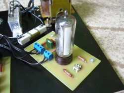
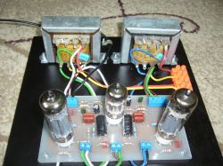
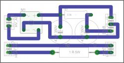
    As Krzysztof writes, it certainly matters, in my case, as it can be seen in the photo, everything is connected chaotically without screens and it sounds beautiful, but I made a shallow lamp from the elements side, but it probably does not matter that much. I have a plate etched somewhere, what you did, buddy, in my free moment I will assemble an amplifier on it and replace the tube and see. I think that there is a problem somewhere in the connections, I recently installed the amplifier instead of the Bambino and selenium capacitor with a rectifier bridge, two electrolytes and two resistors.

    ECL86 and EM84 Tube Amplifier - PCB

    However, when you install it, instead of a large capacitor and selenium, you need to remove the 3.3k resistor from the system or do not mount it on this board, as above, because as a result they will be in parallel and the resistance will decrease.

    I hope you will solve the problem with your amplifier, I am in the process of making the case for mine.

    Best regards ...
  • ADVERTISEMENT
  • #37 17972647
    discawery
    Level 11  
    An unbearable squeak eliminated by swapping the primary winding leads of the speaker transformer, but still a strong hum.
  • #38 17972653
    DJCheester
    Level 26  
    Take a photo of the board as you connected it and put something in, then we will see what is wrong and if there are no measurements according to the bambino scheme.

    Best regards ...
  • #39 17972695
    discawery
    Level 11  
    ECL86 and EM84 Tube Amplifier - PCB
    ECL86 and EM84 Tube Amplifier - PCB


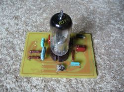
    I upload photos, with the lamp removed, to make it easier to capture the side of elements and connectors.

    I put better quality shielded cables for the signal input and the loudspeaker, it is probably a bit better, but you can still hear a hum, and at higher volume the signal distorts. Do you think it's a massaging problem? Try with some metal chassis, or just connect the potentiometer housing and the speaker transformer directly to the minus path of the power supply? Some people write that straightening the glow helps, but from what I can see, DJCheester didn't do it, and everything is fine.
  • #40 17972710
    tytka
    Level 22  
    discawery wrote:
    but you still hear the hum, and with higher volume the signal distorts


    And so I ask, this filter capacitor in the power supply is not dry by any chance? Have you checked him out?
  • #41 17972736
    discawery
    Level 11  
    One leg is 50uF, and 2 is actually dead ... I will find maybe 2 capacitors at 47uF ...

    Edit:
    The capacitor was replaced with another one from Bambino, also 2x50uF, there was no great improvement, so I mounted the transformer on the Bambino chassis, I put the power supply straight on the chassis and the secondary speaker was also grounded, the hum is much smaller, but still clear, some further tips what else can be done ?
  • ADVERTISEMENT
  • #42 17973071
    zworys
    Level 39  
    Symmetrize the lamp filament power supply.
  • #43 18771942
    Olkus
    Level 32  
    pawelr98 wrote:
    It is a pity to waste ECL86 on mine.

    It would be good if the board was already factory-equipped with a filament voltage multiplier. Then it is easier to switch to PCL lamps.


    Hello. A voltage multiplier is not a good idea. Remember that when under load, the voltage will "sag". After all, duplicators are quite "soft". Better to use a transformer with the correct voltage. Best regards.
  • #44 18772096
    pawelr98
    Level 39  
    Olkus wrote:
    pawelr98 wrote:
    It is a pity to waste ECL86 on mine.

    It would be good if the board was already factory-equipped with a filament voltage multiplier. Then it is easier to switch to PCL lamps.


    Hello. A voltage multiplier is not a good idea. Remember that when under load, the voltage will "sag". After all, duplicators are quite "soft". Better to use a transformer with the correct voltage. Best regards.


    Was a colleague ever built or does he theorize?

    I use voltage doublers very often and have never had a problem with excessive voltage sagging. It's all about capacity.
    A voltage doubler is nothing more than two half-wave rectifiers. For a sufficiently large capacity, there will be no problem.

    In the tube power supply I have the windings 6.3V and 4V connected in series, some more coils are connected to the duplicator.
    I am getting 35-36V for PL504 and PCF82 in series.

    Two schottki diodes and, if I remember, some 4400 uF in each bank.

    Anyway, the filament is not a demanding element, but a resistive element.
    Even if the ripple is a bit high, nothing will happen, as long as the voltage on any of the capacitors does not reach 0V (reverse polarity, often additional diodes are soldered for this or a ready-made bridge is used).
  • #45 18772160
    DJCheester
    Level 26  
    Hello

    I also have a voltage multiplier for this amplifier just in case - the tested one works identically to the PCL86 tube after adding the multiplier.
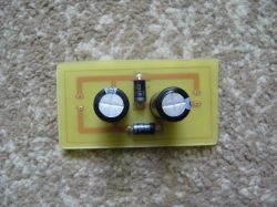
    ECL86 and EM84 Tube Amplifier - PCB

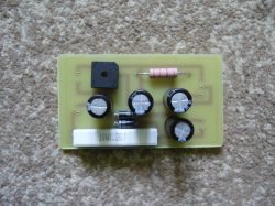
    I also have a separate rectifier on the bridge instead of selenium as a separate power supply board for the Bambino transformer
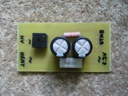
    ECL86 and EM84 Tube Amplifier - PCB

    I used a used ECL86 lamp from the Bambino wreck, but I will not buy a new one, the price in the store is PLN 170 so I will not change to PCL86 I already have a power supply board with a voltage doubler so as not to change the transformer specifically for PCL86
    ECL86 and EM84 Tube Amplifier - PCB

    Currently my amplifier is mounted on a board and it sounds nice all the time waiting for the housing.
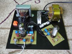
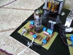
    ECL86 and EM84 Tube Amplifier - PCB ECL86 and EM84 Tube Amplifier - PCB ECL86 and EM84 Tube Amplifier - PCB

    Now work is underway to replace the EM84 lamp with the EM80 - the new control indicator board - like this
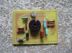
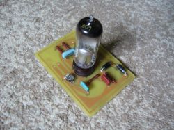
    ECL86 and EM84 Tube Amplifier - PCB ECL86 and EM84 Tube Amplifier - PCB ECL86 and EM84 Tube Amplifier - PCB

    In the future, I will make a second channel on the board with the second control indicator and compare - the board with the indicator lamp can be replaced if necessary, so that finally there are two lamps of the same or if I like one EM84 and the other EM80.

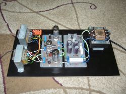
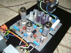
    The design of this amplifier has recently been abandoned a bit due to the ECC83 and 2xEL84 amps - also already done on the countertop - I have to admit that the sound from the EL84 is better - maybe it is a matter of the elements surrounding the tubes, but there is a difference - I will add that all tubes I use are used tubes . This is what the current 2xEL84 amplifier looks like - interestingly, I used a luck for this amplifier from Bambino, with the right connection, these loudspeakers work and the mains one is from Bambino 3 is 40W but if I find that it gives little power, I will attach some of the incandescence to the second such transformer on the board place.
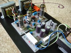
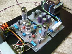
    ECL86 and EM84 Tube Amplifier - PCB ECL86 and EM84 Tube Amplifier - PCB ECL86 and EM84 Tube Amplifier - PCB ECL86 and EM84 Tube Amplifier - PCB ECL86 and EM84 Tube Amplifier - PCB

    So I managed to make a tube amplifier for pennies - I only bought stands and used EL84 tubes - I had ECC83 from a reel ZK120 or 140, I do not remember anymore - I got from Bambino adapters - PCB was made by my own hands - the rest of the elements could be found, so the whole thing could be around PLN 100 and the sound is beautiful.

    Best regards ...
  • #46 18772191
    Olkus
    Level 32  
    Hello. I am currently working on a PCC84 radio project with a tube amplifier. We'll see what happens. Can EM87 be used instead of EM84? Best regards.
  • #47 18772197
    DJCheester
    Level 26  
    Hey - you managed to start the radio - because after the publication a lot of people did and then wrote to me that it does not work and that they have a problem, I was making my PCB for this radio, moreover, the topic described below.

    https://www.elektroda.pl/rtvforum/topic3549270.html

    Be sure to show off what came out of it ;)

    Best regards ...
  • #48 18772583
    Olkus
    Level 32  
    Hello. So far I have made the board itself and I am waiting for the rest of the parts. When I do, I will let you know what came out. Best regards.
  • ADVERTISEMENT
  • #49 20128944
    mariosvd
    Level 10  
    Hello and welcome.
    Congratulations to the author of a great project.
    I assembled this amplifier myself. Now I am at the listening stage.
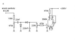
    However, the magic eyes do not react to the beat of the music being played, and after turning the potentiometers to the right, they barely start to react. I used this board with the proposed elements:

    ECL86 and EM84 Tube Amplifier - PCB

    I didn't make any changes to the schematic:
    ECL86 and EM84 Tube Amplifier - PCB

    What element should I replace so that the magic eyes will start reacting at a lower input signal value?
    Thank you very much for every suggestion.
    Regards.
  • #50 20128945
    Krzysztof Kamienski
    Level 43  
    Start by reducing the 56k? resistor value by half.
  • #51 20129295
    DJCheester
    Level 26  
    Hello, replacing the capacitor with a smaller eye will react more vividly, however, when exaggerating with decreasing, it will behave "nervously".

    By the way, I also have a PCB version for the EM80 lamp.

    Regards...
  • #52 20129334
    sq3evp
    Level 37  
    I have not read - is it ready or someone else?
  • #53 20129335
    DJCheester
    Level 26  
    Trafo from the Bambino Adapter or, if you prefer, a turntable.

    Regards...
  • #54 20129392
    sq3evp
    Level 37  
    I was supposed to build a headphone amplifier on tubes, but due to the lack of PCB sockets, nothing came of it.
    I remember powering the glow plug was a current source to extend the time of their operation.
    How do you rate this way of feeding the glow? Could it work?

    The headphones were loaded with min 600?.
  • #55 20129431
    mariosvd
    Level 10  
    DJCheester wrote:
    Hello, replacing the capacitor with a smaller eye will react more vividly, however, when exaggerating with decreasing, it will behave "nervously".

    Thanks for the answer.
    Are you talking about a 10n or 150n capacitor?
  • #56 20129627
    DJCheester
    Level 26  
    I am talking about the big one, the smaller one can also be changed by creating a simple filter for the bandwidth, with the bigger one it will go towards the bass and with the smaller one towards the highs, 10nf is the middle.

    You have to choose it experimentally, you can add a foil capacitor 1u or even 2.2u, it will make the eye react to bass with techno dance, it flashes nicely but when listening to other tracks it is more disturbing.

    It should be checked experimentally.

    Regards...
  • #57 20129839
    pawelr98
    Level 39  
    sq3evp wrote:

    How do you rate this way of feeding the glow? Could it work?

    It will work as much as possible.

    The heating is then longer, but here we have an ideal power supply for PCL86 filaments, where the filament voltage is not constant, only the current is constant.

    According to the catalogs, the difference between western and our local lamps is about 1.5V (13V for Western, 14.5V for our Poles), so the current regulator can make life with this type of lamps easier.
  • #58 20176629
    mariosvd
    Level 10  
    @DJCheester
    Thanks for the hints, however, neither the change of the resistor nor the capacitor gave the expected results.
    I wonder why you used two diodes in series?
    Do they form a voltage doubler together with the capacitor?
    In the network I found such a very similar diagram with one diode:
    ECL86 and EM84 Tube Amplifier - PCB
    Could you please explain to me why you used two diodes? Thank you in advance for your answer.
    Regards
  • #59 20176834
    Krzysztof Kamienski
    Level 43  
    In this diagram, two diodes and a 22 nF capacitor form an evident voltage doubler. Is not it obvious.

Topic summary

The discussion revolves around the design and construction of a tube amplifier utilizing ECL86 and EM84 tubes. The author shares their experience of building a low-power stereo amplifier using recycled components from old turntables and tape recorders. Key topics include the design of the PCB using Eagle and GIMP, the importance of delayed anode voltage for tube longevity, and the challenges faced with filament voltage and hum issues in the amplifier. Participants provide suggestions for improving the design, including the use of PCL86 tubes, voltage stabilization, and grounding techniques to reduce hum. The conversation also touches on the aesthetics of PCB design and the practicalities of tube selection and testing.
Summary generated by the language model.
ADVERTISEMENT