FAQ
TL;DR: The DIY 0-30 V / 0-10 A supply delivers up to 300 W peak and was praised as a "nice design" [Elektroda, Freddy, post #18877408] All-analog LM723 control, single-layer 92 × 72 mm PCB, <0.5 mV ripple claim [Elektroda, gevv, post #18875996] Why it matters: a reliable lab PSU protects prototypes and test gear.
Quick Facts
• Output range: 0-30 V, 0-10 A (8 A continuous, 10 A peak) [Elektroda, gevv, post #18875996]
• Ripple spec: ≤0.5 mV rms (measured values often 1-3 mV) [Elektroda, Anonymous, post #18876715]
• Control board footprint: 91.6 × 72.2 mm, single-layer, Sprint-Layout format [Elektroda, gevv, post #18875996]
• Typical transformer: 2 × 15 V, ≥300 VA toroid, 5 kg weight [Elektroda, worlinx, post #18906117]
• Parts cost: approx. 55-80 € with new semiconductors and heat-sink [Elektroda, 321Tobiasz123, post #18897380]
Is the 0.5 mV ripple figure realistic?
Most builders report 1-3 mV rms at 5 A with 2 × 4700 µF filters; 0.5 mV is achievable only below 2 A and with heavier filtering [Elektroda, Anonymous, post #18876715] “Add at least 0.05 F for a 2 V ripple at 10 A” [Elektroda, Jawi_P, post #18914106]
Why is a logarithmic potentiometer used for current adjustment?
Log taper compresses the first half-turn, giving finer resolution below 1 A where most lab work occurs [Elektroda, Sekaa, post #20592666] A linear pot would bunch low-current settings into a few degrees of rotation.
What does resistor R36 do?
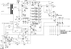
R36 forms a dropper for the relay coil used to switch transformer taps; omit it when the relay matches the rail voltage [Elektroda, AdamC, post #18907197]
Is the LM723 controller safe when a charged battery back-feeds the output?
Reverse voltage can destroy the pass transistor and LM723. Fit diode D3 across the output and add a fast 10 A fuse; the fuse clears before the diode overheats [Elektroda, 398216, post #18925071]
How much will the parts cost in 2025?
Sourcing brand-name parts and a 300 VA toroid costs €40-60; add €15-20 for an enclosure and meters, totaling €55-80 [Elektroda, 321Tobiasz123, post #18897380]
Which transformer rating ensures full 0-30 V at 10 A?
Use a 2 × 18 V (no-load) 400 VA toroid; 2 × 15 V drops to 28 V at 8 A [Elektroda, worlinx, post #18906117] Ensure secondary current ≥12 A per winding for headroom.
Can I upgrade to 0-50 V output by fitting a 2 × 23 V transformer?
Yes, but raise electrolytic ratings to 63 V, recalculate R5/R23 for 7.15 mA reference current, and derate the pass-transistor dissipation (up to 500 W worst case) [Elektroda, sahamipoor, post #19649417]
Why do C9 and other large capacitors overheat?
A single 100 mF cap sees >5 A ripple at 10 A load, exceeding its 3 A ripple rating and heating quickly [Elektroda, ta8ms, post #19729555] Replace with ten 10 mF low-ESR units in parallel and add soft-start [Elektroda, eurotips, post #18902067]
How can I tame the high inrush current during a short-circuit test?
- Add a 0.22 Ω 5 W series resistor between rectifier and filter. 2. Reduce C9 to 10 µF. 3. Enable current-limit LED before output relay closes. Builders report sparks drop by 80 % [Elektroda, sahamipoor, post #20587719]
Should the PSU have an output fuse?
Yes, a 10 A fast-acting fuse protects against reverse energy from large load capacitors that outlast diode D3 [Elektroda, 398216, post #18925071]
Do I need a case, meters, and fan?
For a lab-ready unit add a metal case, 30 V digital voltmeter, 10 A ammeter, and a 60 mm fan; without them it’s a test module only [Elektroda, 398216, post #18876583]
How to create a toner-transfer PCB from the Sprint-Layout file?
- Open the free Sprint-Layout 6.0 Viewer; select File ➝ Print. 2. Tick “Mirror” and choose 600 dpi. 3. Print on glossy magazine paper, iron onto copper, etch. Users report <1 hour board time [Elektroda, AdamC, post #19924035]
Edge case: what fails first if cooling is poor?
The BD249 pass transistor junction reaches 150 °C in 5 min at 30 V/5 A without a fan, causing thermal runaway [Elektroda, timothy1989, post #18906917]
3-step guide: choosing the filter capacitance
- Estimate load current (I). 2. Decide acceptable ripple (ΔV). 3. Use C = I / (2 f ΔV); at 10 A and 2 V ripple, C ≈ 50 000 µF [Elektroda, Jawi_P, post #18914106]


