logo elektroda
logo elektroda
X
logo elektroda

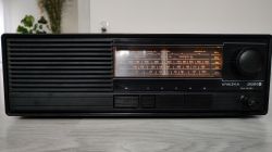
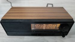
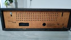
Interior of an old Polish radio receiver UNITRA Sniezka R-207

p.kaczmarek2 14205 97
ADVERTISEMENT
Treść została przetłumaczona polish » english Zobacz oryginalną wersję tematu
  • #61 19015715
    żarówka rtęciowa
    Level 37  
    Hello

    Low frequency power amplifier on which semiconductors? The domestic UL1480 (equivalent to the TBA800) can be used in this type of receiver.
  • ADVERTISEMENT
  • #62 19016215
    ml
    Level 30  
    żarówka rtęciowa wrote:
    Welcome

    Low frequency power amplifier on which semiconductors? A domestic UL1480 (equivalent to TBA800) can be used in this type of receiver.


    Instead of the UL1481, the above-mentioned chip will go directly, but theoretically it is possible that it will be damaged at maximum power, it is dedicated to speakers of min 15 ohm. In practice, with this power supply it should be able to cope. However, soldering it instead of the UL1482 requires circuit changes.
  • #63 19016524
    pawelr98
    Level 39  
    Rezystor240 wrote:
    .
    I currently have a Tambourine, it's reasonably restored, tuned and even worked out correctly for me. It receives about a dozen stations.
    .

    And the heterodyne coil was the friend's 3.5 or 2.5 coil ?
    It just makes me wonder if it was just my copy that had it screwed up that it had 2.5 coils and wouldn't tune.
    I had two BF199s landed in the head in this radio (no BF240s in the shop).

    Sometimes I am tempted to modify the volume potentiometer.
    Because I basically only operate at low levels. I barely turn it to the right and it's already a bit too loud. Put in a series resistor and by the way check if by chance there is a linear instead of a logarithmic one for some reason.
  • #64 19016840
    Rezystor240
    Level 42  
    pawelr98 wrote:
    A friend's heterodyne coil was 3.5 or 2.5 turns ?
    It just makes me wonder if it was just my copy that had it screwed up that it had 2.5 coils and wouldn't tune.


    To be honest I can't remember, but I know there was no need to put in a new coil, I just stretched the original one from what I remember. So more like 3, 5 but don't want to mislead. I'll take a clear photo tomorrow and it will be visible.

    Added after 1 [minute]: .

    The potentiometer in this equipment has a switch, so replacing it won't be obvious. Well, unless you have a suitable potentiometer for replacement.
  • #65 19017109
    breshnew
    Level 14  
    I regret that I didn't take the Fagot and the Sudeten from my old flat. This Fagot in particular is such an "almost" tube, but without the drawbacks of a tube. As for the questions about coil dimensions: in mono I managed to tune without changing the number of coils, only in the TSH-113 (GF-101) I unfortunately had to select the double bandpass filter coils empirically, vide: Link .
    on the advice of my hugely respected Andrew L, and that's because I've probably screwed them up myself trying to glue them together with capacitance bending etc. And if someone has an HF generator and spectrum analyser somewhere, you don't even need to rely on schematics, just tune by measuring the stages one by one.
    And it's worth it by ear, too, as long as you don't mess it up any more - any such radio saved is a treasure!
  • ADVERTISEMENT
  • #66 19017161
    pawelr98
    Level 39  
    Rezystor240 wrote:
    pawelr98 wrote:
    And the heterodyne coil was a friend's 3.5 or 2.5 turns ?
    It just makes me wonder if it was just my copy that had it screwed up that it had 2.5 coils and wouldn't tune.


    To be honest I can't remember, but I know there was no need to put in a new coil, I just stretched the original one from what I remember. So more like 3, 5 but don't want to mislead. I'll take a clear photo tomorrow and it will be apparent.
    .

    The 3.5 convolution is from the documentation of the "Jubilat" radio, which has an identical head (by the way you can see the cost-cutting such as the lack of a diode at the coil in the heterodyne, although the place is there).
    At 2.5 turns for the CCIR band, the oscillations of the heterodyne at the bottom of the band disappeared.

    After making a new coil, the radio holds the entire CCIR band normally, and the tuning was done without any major problems. However, a capacitor had to be soldered in series with the heterodyne unit (the effect of higher inductance) in order to stretch the band all the way down.

    My struggle with this radio is described here.
    https://www.elektroda.pl/rtvforum/topic3484149.html

    Honestly, I would still be happy to replace the original BC211/BC313 power amplifier transistors with BD139/BD140 to improve the allowable output current and install a new 8Ω speaker (the original is not in the best condition, and it is a bit difficult to get a new 15Ω speaker).
  • #67 19017239
    kris8888
    Level 39  
    ml wrote:
    Let me disagree with what colleague ads wrote above.
    These receivers are easy to tune, rarely do you need to change coils and if you do, it is for the coils with higher inductance, reducing the capacitance of capacitors in resonant circuits which results in broadening the received band and shifting it upwards (CCIR) . Unfortunately, the sensitivity and, above all, selectivity of these and similar radios is poor due to the simple ukf heads and HF path. It is possible to change the input transistor of the head to, say, BF240 but then the head or excitation at tuning to maximum sensitivity.
    .
    That's right, I recently tuned my Snowbird (but R-206 model) according to a guide available even here on Elektroda and it started practically immediately. The coils did not need to be moved at all. I was even surprised by the very good sensitivity, better than my Denon tuner. On a piece of cable reception of practically all stations without noise. Maybe because it is, however, only mono reception. Only the selectivity leaves a lot to be desired, but this is understandable. As far as the sound quality is concerned, I wouldn't "hang the dogs" on it so much. It is certainly much better than many of the plastic alarm clocks currently on sale. The only thing that surprises me is the incomprehensible saving of a full bridge rectifier in the R-206 model.
  • ADVERTISEMENT
  • #68 19017311
    Rezystor240
    Level 42  
    breshnew wrote:
    any such radio saved is a treasure!


    And that's what matters most
  • ADVERTISEMENT
  • #69 19017396
    kris8888
    Level 39  
    pawelr98 wrote:
    .
    Well, and the equipment from the USSR is cool too. Thick cast frame, laminate covered with thick varnish and a different look at technology.

    I don't know why my colleague has such enthusiasm for equipment from the former USSR. It throws me off when I still find one by accident to repair or dismantle. Tragic quality of components, especially capacitors, but also semiconductors susceptible to damage, also mechanical, tragic and primitive assembly, paper laminate and often over-engineering. Perhaps only the MŁT resistors are worthy of attention and reuse. After all, our Unitra equipment is a fairy tale. Of course, I'm writing about equipment for general use, because, for example, equipment for military use is in a completely different league.
  • #70 19017572
    pawelr98
    Level 39  
    kris8888 wrote:
    pawelr98 wrote:
    .
    Well, and the equipment from the USSR is cool too. Thick cast frame, laminate covered with thick varnish and a different look at technology.

    I don't know why my colleague has such enthusiasm for equipment from the former USSR. It throws me off when I still find one by accident to repair or dismantle. Tragic quality of components, especially capacitors, but also semiconductors susceptible to damage, also mechanical, tragic and primitive assembly, paper laminate and often over-engineering. Perhaps only the MŁT resistors are worthy of attention and reuse. After all, our Unitra equipment is a fairy tale. Of course, I am writing about equipment for general use, because, for example, equipment for military applications is a completely different league.


    Quite a lot of measuring equipment and even some utility equipment was made just like "military" equipment.

    And why do I like equipment from the USSR ? Because it is different. A different view of technology, different components. It's not as boring as in unitra, that every other radio has the same head and has 1:1 western components.
    And I happen to have a lot of parts from the former USSR so repairing it is no problem for me.
  • #71 19019399
    Gismot
    Level 18  
    kris8888 wrote:
    .
    Often over-engineered.
    .
    And our audio equipment is again trimmed to the bare minimum. :)

    kris8888 wrote:
    paper laminate
    .
    PCB laminate quality similar to ours.
  • #72 19621064
    glass2
    Level 12  
    pawelr98 wrote:
    3.5 turns are evident from the documentation of the "Jubilat" radio, which has an identical head (by the way, you can see the cost-cutting such as the absence of a diode at the coil in the heterodyne, although the space is there).
    At 2.5 turns for the CCIR band, the oscillations of the heterodyne at the bottom of the band disappeared.

    After making a new coil, the radio holds the entire CCIR band normally, and the tuning was done without any major problems. However, a capacitor had to be soldered in series with the heterodyne unit (the effect of higher inductance) in order to extend the bandwidth all the way down.


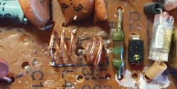
    Hello. I'm joining the discussion because I've just struggled with a Snowball R-207 not so long ago.It's been "buried" so this makes the task more difficult. Currently it is behaving strangely because when I change the frequency of the heterodyne with the rotary capacitor (normal tuning), the frequency from 118.7 MHz goes down nicely, you can hear a lot of stations and then at 102 MHz the heterodyne chokes, stops working and by turning the knob further after about 2cm on the scale it starts working again up to 96 MHz. This is not a rotary capacitor problem because I can move this fade on the scale. I would very much appreciate suggestions as to what could be the reason for this, and I would also appreciate information on how to make coils L2, L3 and L4. They have been rummaged around. I currently have L2 6 coils fi 0.2 by fi 6mm, and L3 and L4 are 2.5/3.5 coils fi 0.4 by fi 5mm. I would be very grateful for any help.
  • #73 19622166
    pawelr98
    Level 39  
    L4 is supposed to be 3.5 turns and half tapped at 1.75 turns, if a colleague looks at what the soldering points are, it will be immediately apparent how to wind.
  • #74 19622421
    glass2
    Level 12  
    pawelr98 wrote:
    L4 is supposed to be 3.5 coils and half tapped for 1.75 coils, if a colleague looks at what the solder points are, it will be immediately apparent how to wind.
    .
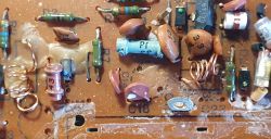
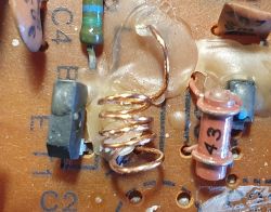
    Thank you for your reply. Coil L3 and L4 are like one with a tapping, or two connected together. On the PCB and on the schematic, L3 and L4 are present. My understanding is that: L3+L4 = 3.5 coils with a half-tap. I don't have the original coil but from the photo I looked at it is not a symmetrical winding. L4 has 1 more winding.

    I have just now found the answers to my questions. :D .
    I have documented in the attached photos:
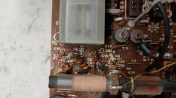
    Interior of an old Polish radio receiver UNITRA Sniezka R-207
    L2 = 5 coils
    Interior of an old Polish radio receiver UNITRA Sniezka R-207
    L4 = 3 coils + L3 = 2 coils.
    Interior of an old Polish radio receiver UNITRA Sniezka R-207 .

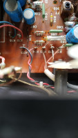
    PCB photos of a head similar to the Snowball (I have no idea from what, as there are no captions)
    I think this thread can be closed.
  • #75 19660912
    Anonymous
    Level 1  
  • #76 19661050
    Janusz_kk
    Level 39  
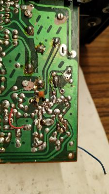
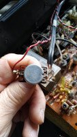
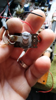
    It looks like ground, so solder it to the third pin of the potentiometer, in the first photo that top pin, where those wires from the cable are not in the screen.
  • #77 19661151
    Anonymous
    Level 1  
  • #78 19661155
    Tytus Kosiarski
    Level 16  
    From what I remember, this black wire was not soldered anywhere at the potentiometer. It acted as a shield for the red wire from the potentiometer tapping and was only soldered at one end to pin K23. Leave it as you have it now, just make sure that the other end of this black wire doesn't come into contact with anything when the potentiometer is mounted.

    Even the schematic diagram from the initial post shows that there are only 4 wires connected to the potentiometer.
  • #79 19661176
    Janusz_kk
    Level 39  
    Actually, the potentiometer is soldered to the screen, I've now matured that, i.e. the black slack wrapped over the red.
  • #80 19661269
    Anonymous
    Level 1  
  • #81 19661641
    glass2
    Level 12  
    My suggestion is similar to the previous ones. This black wire is the ground and if it necessarily "must" be soldered then to the sheet metal on the potentiometer axis. Where the shield is soldered. It can also be free, because the shield, already makes this connection. Regards.
  • #82 20215702
    szejker89
    Level 14  
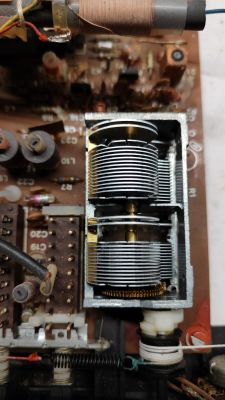
    My father-in-law brought me an R-207 from the "dump" and the radio was just buzzing. After taking it apart, to my surprise, ours was already here ;) The radio is tuned and all I had to do was to repair a track that had broken (cracked laminate). However, it is strangely tuned.... I found a schematic, with capacitor values for the tuning, which differs from what is done in my copy. Capacitor C2 replaced with 15pF instead of 18pF, C8 cut out, C14 is 15pF, C17 cut out. It was screwed with "something" of the F1 description, L1 has no case (unless that's how it is originally), fiddled with coils L3 and L4, and coil L2 stretched at the ends. The air capacitor has two plates slightly bent off. The shield which is glued to the case was not connected.
    The radio receives very well, but buzzes. I wonder if this is the fault of the electrolytes or maybe due to these cut capacitors.
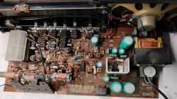
    Interior of an old Polish radio receiver UNITRA Sniezka R-207 Interior of an old Polish radio receiver UNITRA Sniezka R-207 Interior of an old Polish radio receiver UNITRA Sniezka R-207 Interior of an old Polish radio receiver UNITRA Sniezka R-207 Interior of an old Polish radio receiver UNITRA Sniezka R-207 .


    I'm going to get down to cleaning the switches, potentiometer, replacing electrolytes (all of them without exception), and all the cosmetics. Should I leave it alone, or experiment with adding capacitors C8 and C17 which are cut out? Unfortunately I don't have any measuring instruments apart from a multimeter and a digital Chinese oscilloscope with a 1kHz generator.
  • #83 20215718
    Janusz_kk
    Level 39  
    These cut-outs have nothing to do with the buzz, the buzz is caused by dead electrolytics or an amplifier.

    szejker89 wrote:
    The air capacitor has two plates slightly bent.

    Don't touch this, this is the factory tuning for long wave.
  • #84 20217094
    szejker89
    Level 14  
    It turned out that capacitor C8 is inserted on the other side of the board, with a capacitance of 43pF. Adding C17 makes no difference. The electrolytes are in very good condition, I only replaced 2 pieces which had a higher ESR. The screen on the chassis has to be disconnected because the sensitivity decreases very much when connected. Buzzing has not stopped, but it depends on the antenna and feed cable setting, on some stations there is no buzz and on others there is. Switches cleaned with Kontakt S fluid without taking them apart, potentiometer cleaned mechanically without any chemistry. I wish I had pictures of the radio when I got it.... This is how it looks now :) .

    Interior of an old Polish radio receiver UNITRA Sniezka R-207 Interior of an old Polish radio receiver UNITRA Sniezka R-207 Interior of an old Polish radio receiver UNITRA Sniezka R-207 .

    P. S. after inserting the photos I ran the veneer over with isopropanol to get rid of the dirt, the front was lightly run over with K2 Bono blackener and the scale was polished with Tek P1 polish. It looks like a brand new saloon :) .
  • #86 20218072
    szeryf3
    Level 29  
    @szejker89 well another iconic radio saved.
    I have such a radio in my kitchen and it has minor problems with strong station reception. This is the fault of where the radio is placed.
    But the radio is happy.
  • #87 20218145
    Anonymous
    Level 1  
  • #88 20218441
    szejker89
    Level 14  
    At my place, I noticed that the strongest stations buzz the most. In addition, when I wanted to wrap the cable behind the radio so that it did not wander on the floor, the buzzing increased significantly. Re-positioning the antenna (for the time being a simple wire) had no effect, moving the coiled cable away from the antenna also had no effect. Uncoiling the mains cable helped. Maybe someone can come up with an idea? I've already read about the buzzing problem in this radio but no one has solved it completely. And would using a ferromagnetic core on the mains cable make any sense?
  • #89 20218457
    Janusz_kk
    Level 39  
    szejker89 wrote:
    In addition, when I wanted to somehow wrap the cable behind the radio to keep it from wandering on the floor, the buzzing increased a lot.
    .
    You have a network induction somewhere inside, see if you have the grounds correct on the mcz amp and volume potentiometer, there could also be cold or oxidised solders.
  • #90 20218501
    glass2
    Level 12  
    This radio has an incandescent light bulb, I suggest disconnecting it for testing. It should help.
    If this is the case, I suggest routing the power supply to the bulb differently.

    Regards

Topic summary

The discussion centers on the UNITRA Sniezka R-207, a Polish radio receiver from the 1980s/90s, focusing on its interior, tuning, and restoration. The radio features a veneered chipboard case with a plastic front panel marked "Snow Diora," mechanical tuning via a large knob, and a volume potentiometer. Users share experiences rescuing and refurbishing these radios, noting their durability and historical value despite modest sound quality and selectivity. Technical details include the use of air coils (L2, L3, L4) with specific winding turns (e.g., L4 at 3.5 turns with a half tap), and the heterodyne coil requiring careful tuning or rewinding to cover the CCIR band (87.5–108 MHz). The power amplifier often uses UL1481/UL1482 or equivalents like TBA810, with suggestions to replace transistors (e.g., BC211/BC313 with BD139/BD140) and speakers for improved performance. Common issues include a 100 Hz hum caused by power supply grounding design, which can be mitigated by additional grounding wires or disconnecting the incandescent bulb circuit. Electrolytic capacitors, especially from Elwa, generally remain in good condition unless exposed to adverse environments, but some users recommend checking and replacing those with high ESR. Modifications such as adding a 0.47 µF polyester capacitor across rectifier diodes help suppress high-frequency interference. The discussion also covers tuning techniques using frequency indicators, RTL-SDR devices, and voltmeters on the FM demodulator output. Some users caution against invasive tuning that alters original parameters, suggesting band converters for adapting to different frequency standards (OIRT vs. CCIR). The thread includes comparisons with other Polish models (R-208 Sudety, R-206 Snowbird, Taraban series) and mentions stereo decoder modifications using UL1621 ICs. The overall consensus appreciates the radios' simplicity, durability, and cultural significance, despite limitations in audio fidelity and component quality compared to Western equipment of the era.
Summary generated by the language model.
ADVERTISEMENT