FAQ
TL;DR: Re-casing a €12 Chinese DDS generator in a CD-ROM box delivers ±1 Hz frequency agreement and “very respectable” stability [Elektroda, dudik56, #19258591; Elektroda, kapi11711, #19259677] while upgraded wiring adds 3-core 0.5 mm² cable and ≥6 mm 230 V spacing.
Why it matters: Smart safety and layout tweaks turn a bare board into a reliable lab signal source for pennies.
Quick Facts
• Frequency span: 0.01 Hz – 10 MHz typical for AD9850/AD9833 Chinese DDS boards ("DDS Function Generator").
• Accuracy: ≤ 1 Hz deviation at 1 kHz vs. counter [Elektroda, dudik56, post #19258591]
• Output swing: 0 – 20 Vpp selectable with onboard op-amp [“H11887 install manual”].
• Mains section: 2 × 12 V, 2.5 VA transformer, 63 mA fuse [Elektroda, dudik56, post #19259195]
• Safety clearance: 6 mm PCB-to-case gap after fix [Elektroda, dudik56, post #19259195]
1. Which DDS board is used and what range does it cover?
The build uses the common H11887/AD9850 DDS module. Its sine, square and triangle outputs span approx. 0.01 Hz to 10 MHz, with 0.01 Hz resolution according to the kit datasheet [“H11887 install manual”].
2. How precise is the frequency output?
At 1 kHz the module’s display and an external counter differed by no more than 1 Hz, giving a 0.1 % error budget [Elektroda, dudik56, post #19258591]
3. How can I eliminate offset or crossover distortion in the waveform?
Replace the stock LM358 with TL062; users reported a smooth zero-crossing after the swap [Elektroda, dudik56, post #19261095] “It’s not offset, rather cross-distortion” clarifies a peer [Elektroda, zgierzman, post #19261128]
4. What power-supply topology was chosen?
A 2 × 12 V, 2.5 VA PCB transformer feeds LM7812, LM7912 and LM7805 linear regulators, yielding +12 V, –12 V and +5 V rails [Elektroda, dudik56, post #19257919]
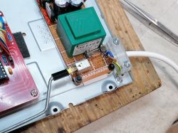
5. How do I route 230 V safely inside a metal case?
Keep live traces ≥ 6 mm from metal, insulate the standoffs, and use a rear power switch to shorten mains wiring [Elektroda, dudik56, #19259195; Elektroda, ^ToM^, #19259830].
6. Is a protective-earth (PE) conductor mandatory here?
For Class II, low-power gear PE is not obligatory, yet many builders add a 3-core cable for extra safety [Elektroda, U92, post #19260986] The author later swapped to a 3-core 0.5 mm² lead [Elektroda, dudik56, post #19263396]
7. Which power switch fits a shallow front panel?
A miniature PCB switch actuated by a long plastic rod lets you mount mains components at the rear while retaining a front button, a practice used by Philips and Hameg instruments [Elektroda, ^ToM^, post #19259830]
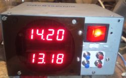
8. How can I turn an old optical-drive shell into a lab case?
How-To:
- Strip the DVD-ROM, keep the steel frame and aluminium front.
- Mill openings for BNCs, display and keypad; bond a Dibond overlay for labels.
- Mount boards on plastic standoffs and close with retained screws. Total time: ≈ 2 h [Elektroda, dudik56, post #19257919]
9. What mains cable and fuse ratings should I choose?
Match fuse to worst-case short-circuit. The build uses a 63 mA glass fuse and a 3-core 0.5 mm² cable, providing > 4× thermal headroom [Elektroda, dudik56, post #19261660]
10. Can I obtain continuous frequency tuning instead of decade steps?
Standard firmware steps digitally; for audio sweeps you can add an encoder-driven “fine” menu or upgrade to an AD9834 board offering 0.004 Hz resolution [“DDS Function Generator”].
11. What are common failure or hazard edge cases?
Edge cases include standoff creep reducing clearance below the IEC 61010 5.5 mm minimum, and a loose live wire touching the case, causing shock risk. A 3-core cord and strain-relief clamp mitigate both issues [Elektroda, pawlik118, post #19259133]
12. Where can I get full schematics and code?
Download the original PDF manual from Dropbox [Elektroda, dudik56, post #19258791] or check the open-source design on Electronics-Lab (“DDS Function Generator”).
 and when he gets there I will change him. OKAY?


