logo elektroda
logo elektroda
X
logo elektroda

LED weather station with NTP clock and calendar

efi222 16428 63
ADVERTISEMENT
Treść została przetłumaczona polish » english Zobacz oryginalną wersję tematu
  • #31 19282331
    pier
    Level 24  
    What coverage do you get on ESP 12 with ESP NOW? Does ESP NOW have any RRSI checking function?
  • ADVERTISEMENT
  • #32 19282398
    khoam
    Level 42  
    pier wrote:
    Does ESP NOW have any RRSI checking function?

    Is it about the RSSI? In ESP-NOW mode you can check the signal strength of received packets, but for this you need to define a callback function for promiscuous mode (code for ESP32):
    Code: C / C++
    Log in, to see the code

    Or use Arduin WiFi.RSSI () and scan slaves :) Link
  • ADVERTISEMENT
  • #33 19282402
    efi222
    Level 19  
    The range is similar to working via wifi. Somewhere I read that it is supposed to be bigger by ESP-Now, but somehow I didn't notice it. Instead of Rssi in the measurement module, I used the out of range signaling on the LED. There is a button which, when pressed, sends data to the receiver. If the module is within range of the station or the repeater, the diode is off. If it flashes, the module is out of range.
  • ADVERTISEMENT
  • #34 19282414
    khoam
    Level 42  
    efi222 wrote:
    Somewhere I read that it is supposed to be bigger by ESP-Now, but somehow I didn't notice it.

    The ESP-NOW protocol does not increase the range, it works in the same band as the standard WiFi 2.4. However, it allows you to increase the speed of data transfer.
  • #35 19282460
    efi222
    Level 19  
    I tested the idea of my colleague krzbor with connecting the Master to the wifi network for a while to save the settings. Everything works fine but after disconnecting the power, ESP does not remember the settings, or at least the channel. Maybe someone knows if there is a channel number in the ESP8266 network credentials? Because it looks like not.
  • #36 19282472
    khoam
    Level 42  
    efi222 wrote:
    Maybe someone knows if there is a channel number in the ESP8266 network credentials? Because it looks like not.

    You have to do it yourself, e.g. by writing to the emulated EEPROM.
  • #37 19282488
    efi222
    Level 19  
    So you still have to cheat the Master with the non-existent access point to change this unfortunate channel .. :)
  • #38 19282503
    khoam
    Level 42  
    efi222 wrote:
    So you still have to cheat the Master with the non-existent access point to change this unfortunate channel.

    Exactly, please write what you understand the definition of "Master". I admit that I got a bit lost, and the ESP-NOW documentation does not contain terms like "master" or "slave".
  • #40 19282615
    khoam
    Level 42  
    efi222 wrote:
    Master, i.e. transmitter and Slave, i.e. receiver, Combo - a mix of the two.

    So be it :) Although the term "peer" is used in newer documentation, and this one can transmit and receive, both are always available.
    If Master is a transmitter, what access point is it?
  • #41 19282631
    krzbor
    Level 27  
    efi222 wrote:
    I tested the idea of my colleague krzbor with connecting the Master to the wifi network for a while to save the settings. Everything works fine but after disconnecting the power, ESP does not remember the settings, or at least the channel. Maybe someone knows if there is a channel number in the ESP8266 network credentials? Because it looks like not.
    Somewhere on the electrode there was something about a quick connection to deep sleep - it was about remembering all the necessary parameters for communication over WiFi in order to maximize the length of battery life.
  • #42 19282674
    efi222
    Level 19  
    khoam wrote:
    efi222 wrote:
    Master, i.e. transmitter and Slave, i.e. receiver, Combo - a mix of the two.

    So be it :) Although the term "peer" is used in newer documentation, and this one can transmit and receive, both are always available.


    Well, I didn't make it up :)
    esp_now_set_self_role (ESP_NOW_ROLE_CONTROLLER); // set the transmitter
    esp_now_set_self_role (ESP_NOW_ROLE_SLAVE); // set the receiver
    esp_now_set_self_role (ESP_NOW_ROLE_COMBO); // transmitter and receiver

    At least that's the case for ESP8266. And I have not met anyone else configuring. What you are writing about is probably for ESP32, and I didn't do that :)

    khoam wrote:
    If Master is a transmitter, what access point is it?


    Well, the idea was not to combine with a fictitious network to change the channel in the transmitter, but to connect to the wifi network for a while to save the network credentials. It did nothing, because the credentials do not include the wifi channel.
  • #43 19282691
    khoam
    Level 42  
    efi222 wrote:
    Well, the idea was not to combine with a fictitious network to change the channel in the transmitter, but to connect to the wifi network for a while to save the network credentials. It did nothing, because the credentials do not include the wifi channel.

    It seems to me that the information about the channel can be downloaded with the WiFi.channel () function, after connecting to the AP or after creating your own AP.
  • ADVERTISEMENT
  • #44 19282705
    krzbor
    Level 27  
    Found this article. This was the link from the electrode: Link The author saves the data in the RTC memory. In your case it is enough to write WiFi.channel () in EEPROM (simulated in ESP);
  • #45 19283924
    pier
    Level 24  
    krzbor wrote:
    Found this article. This was the link from the electrode: Link The author saves the data in the RTC memory. In your case it is enough to write WiFi.channel () in EEPROM (simulated in ESP);


    Thanks for this link. You can read very interesting things there.
  • #46 19284625
    efi222
    Level 19  
    krzbor wrote:
    Found this article. This was the link from the electrode: Link The author saves the data in the RTC memory. In your case it is enough to write WiFi.channel () in EEPROM (simulated in ESP);


    The article is very interesting, only that if I understand correctly the settings "disappear" after disconnecting the power supply.
    I have used the WiFi.channel () function before, but I did not go in that direction. I scanned WiFi networks. A little pointless. And as it turned out, the function without parameters returns the channel of the network to which the ESP is connected.
    It was straight ahead. Just not to enter the network credentials in the transmitter configuration, I connect to the AP running in the ESP_NOW receiver. These settings are hard in the receiver code. The condition is that the station must be connected to the WiFi network. Next, configurations of measuring modules.
    In the screenshots, the configuration of the sensor module of the earlier version and the new one.

    LED weather station with NTP clock and calendar
    LED weather station with NTP clock and calendar
    LED weather station with NTP clock and calendar


    In the new version, you do not need to know and enter the WiFi channel of the network. Just run the transmitter configuration, set the number and interval and save everything. The message on the module configuration page is just an example. You can do it any way you like. For example, display the channel number again. The new transmitter code is attached. Many thanks to my colleagues krzbor and khoam for inspiration :)
  • #47 19284672
    khoam
    Level 42  
    Then you have to do the ESP software update via OTA :)
  • #48 19284685
    efi222
    Level 19  
    Mercy..... :D . I don't have the strength anymore ... 40 software downloads. People must have read these codes. It is strange that no one reports amendments, etc. Maybe someone is willing to do it OTA and will implement it in the code :) . On the other hand, the Atmegi has to be programmed over the cable anyway. (unless there's something I don't know ..)
  • #49 19284690
    khoam
    Level 42  
    efi222 wrote:
    On the other hand, the Atmegi has to be programmed over the cable anyway. (unless there's something I don't know ..)

    :) Link
  • #50 19284751
    krzbor
    Level 27  
    efi222 wrote:
    Mercy..... :D . I don't have the strength anymore ... 40 software downloads. People must have read these codes. It is strange that no one reports amendments, etc. Maybe someone is willing to do it OTA and will implement it in the code :) . On the other hand, the Atmegi has to be programmed over the cable anyway. (unless there's something I don't know ..)
    I thought so too, but all OTA support in ESP is one (really) line of code (and including the library). It is easier to make an OTA in ESP than to turn off WiFi :) Anyway, when I did it, I wondered why it was so late :) Now I am uploading the new version to the server and ESP is downloading it - no more cables!

    Added after 11 [hours] 2 [minutes]:

    pier wrote:
    krzbor wrote:
    Found this article. This was the link from the electrode: Link The author saves the data in the RTC memory. In your case it is enough to write WiFi.channel () in EEPROM (simulated in ESP);


    Thanks for this link. You can read very interesting things there.

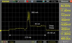
    It is worth reading the entire cycle (3 parts). In addition to the description and code, we have interesting charts there. To make it easier, I collected these links:
    Part 1
    Part 2
    Part 3
    Supplement
  • #51 19285364
    efi222
    Level 19  
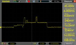
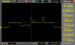
    I read this tutorial once. Very interesting. But I decided to broadcast ESP-NOW. It's just faster. And with battery power, however, it has a significant impact on the battery life. I also made an oscillogram of the transmitter's operation (current consumption). You can see that the sending itself takes about 20ms. The rest of the time is waking up, taking measurements and falling asleep. I also tested the ESP8285. With this module you can save about 50ms. The module has an integrated flash with the MCU.

    LED weather station with NTP clock and calendar

    And here is the effect of the capacitor on the ESP8266 power supply. Interestingly, I did not notice any changes in the range.

    LED weather station with NTP clock and calendar
    LED weather station with NTP clock and calendar
    LED weather station with NTP clock and calendar

    I added a package with all PCBs for the project to the first post. I make the tiles myself, so they are ready for thermal transfer.
  • #52 19300435
    khoam
    Level 42  
    efi222 wrote:
    I also tested the ESP8285. With this module you can save about 50ms.

    I do not understand this, i.e. what exactly can be saved. As for the power consumption of both modules, according to the manufacturer's documentation for ESP8266:

    LED weather station with NTP clock and calendar

    and for ESP8285:

    LED weather station with NTP clock and calendar

    Perhaps you compared the current draws of different PCBs with those chips, and that's a bit different.
  • #53 19300452
    efi222
    Level 19  
    It's not about power consumption, but about waking up, measuring and sleeping. Integrated memory probably speeds up data exchange. I compared both modules with a similar configuration.
    There is ESP 8266 in the oscillograms.
  • #54 19300502
    khoam
    Level 42  
    The awakening time from deep-sleep is primarily the boot time of ESP, and this depends on many factors. Link
  • #55 19300513
    efi222
    Level 19  
    This is the transmitter code snippet from this project. I personally checked all the sleep options. The former works the fastest.

    ESP.deepSleepInstant (SLEEP_TIME * inter, WAKE_NO_RFCAL);
    // ESP.deepSleepInstant (SLEEP_TIME * inter, WAKE_RFCAL);
    //ESP.deepSleepInstant(SLEEP_TIME * inter, RF_NO_CAL);
    //ESP.deepSleepInstant(SLEEP_TIME * inter, WAKE_RF_DEFAULT);
    //ESP.deepSleep(SLEEP TIME * inter);

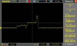
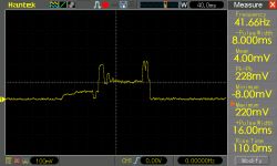
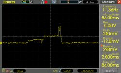
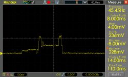
    Measurement module oscillograms. Differences in the way ESP8266 sleeps. These aren't big differences, but still.

    WAKE_NO_RFCAL - 220 ms
    LED weather station with NTP clock and calendar

    WAKE_RFCAL - 260 ms
    LED weather station with NTP clock and calendar

    RF_NO_CAL - 230 ms
    LED weather station with NTP clock and calendar

    WAKE_RF_DEFAULT - 250 ms
    LED weather station with NTP clock and calendar

    DeepSleep without options - 360 ms
    LED weather station with NTP clock and calendar

    Interestingly, manual wake-up - module reset with the button, introduces an additional boot delay for all modes, approx. 120 ms
    DeepSleep without options - manual reset - 480 ms
    LED weather station with NTP clock and calendar

    When waking ESP from the timer by GPIO16 it looks like in the waveforms above.
  • #56 19300792
    khoam
    Level 42  
    efi222 wrote:
    Interestingly, manual wake-up - module reset with the button, introduces an additional boot delay for all modes, approx. 120 ms

    Rather, it shouldn't be strange, since additional peripherals initialization procedures are performed - after a "manual" reset it looks like it does after powering up.

    efi222 wrote:
    When waking ESP from the timer by GPIO16 it looks like in the waveforms above.

    Decide with a timer or external wake-up? :)

    Generally, these times are a bit long. What is the benchmark for recognizing that ESP has awakened?
  • #57 19300835
    efi222
    Level 19  
    khoam wrote:
    efi222 wrote:
    Interestingly, manual wake-up - module reset with the button, introduces an additional boot delay for all modes, approx. 120 ms


    Decide with a timer or external wake-up? :)


    Well, GPIO16 is physically connected to the Reset input. This is not a timer wake up?

    khoam wrote:
    Generally, these times are a bit long. What is the benchmark for recognizing that ESP has awakened?


    The point of reference is the current consumption. And the times are long, because the module has to take measurements from the sensors after waking up, send them and go back to sleep.
  • #58 19300862
    khoam
    Level 42  
    efi222 wrote:
    Well, GPIO16 is physically connected to the Reset input. This is not a timer wake up?

    Yes, this is a wake-up timer, and external wake-up in the case of ESP8266 is by pressing reset when ESP.deepSleep (0) is set ;)

    efi222 wrote:
    The point of reference is the current consumption. And the times are long, because the module has to take measurements from the sensors after waking up, send them and go back to sleep.

    You can, of course, take such a benchmark, but the results will not be very objective.
  • #59 19300894
    efi222
    Level 19  
    khoam wrote:
    efi222 wrote:
    Well, GPIO16 is physically connected to the Reset input. This is not a timer wake up?

    Yes, this is a wake-up timer, and external wake-up in the case of ESP8266 is by pressing reset when ESP.deepSleep (0) is set ;)


    Well, I did not mention the external wake-up :)
    I think I got lost ...

    khoam wrote:

    efi222 wrote:
    The point of reference is the current consumption. And the times are long, because the module has to take measurements from the sensors after waking up, send them and go back to sleep.

    You can, of course, take such a benchmark, but the results will not be very objective.


    I'm sorry, I don't know any other way ... :)
  • #60 19331186
    yogi009
    Level 43  
    A very nice project, a definite plus from me.

Topic summary

The discussion revolves around the construction and functionality of a custom LED weather station utilizing seven-segment displays instead of traditional LCDs. The device features a range of measurements including temperature, humidity, atmospheric pressure, and time, with excellent visibility in various lighting conditions. Participants discuss the materials used, such as veneered MDF for the housing, and the integration of ESP8266 modules for data transmission in both AP and station modes. Concerns about sensor placement, power consumption, and the durability of components are addressed, along with suggestions for using alternative sensors like HTU21D for improved accuracy. The conversation also touches on PCB design, software updates, and the potential for expanding the station's capabilities.
Summary generated by the language model.
ADVERTISEMENT