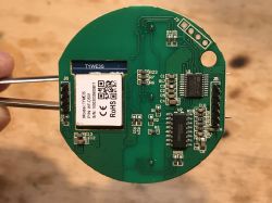
Hello my dears. I'd like to invite you to a short test of the Tuya/SmartLife WiFi-controlled can switch/dimmer, model WF-DS01. Here I will show its interior, discuss how it is built, draw its schematic and finally I will also show on an oscilloscope how the triac power control looks like. As is customary, I will also check how the situation is with its alternative open source firmware.
Buy Tuya/SmartLife WiFi dimmer
I found the product under the keyword Wifi Dimmer Switch EU Plug Wall Light Touch Switch TUYA/Smart Life APP for Alexa for about $20 (in our PLN 80). It is also worth searching for this product by model name: WF-DS01. I made the purchase already after 1 July 2021, i.e. after the introduction of adding VAT to shipments, but there was no problem with the purchase anyway (the additional amount is still added when buying the item).
Offer screenshot:
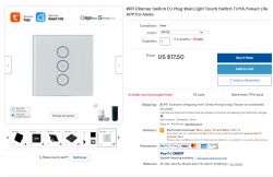
Two colours of the product are available.
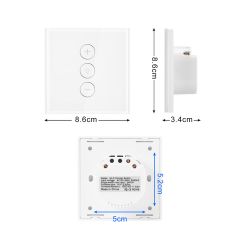
Specification by seller:
Quote:
Size: 86 x 86 x 35 mm
Colors: Black, White,
Material: Alloy+Crystal Glass
Warranty: 1 year
Certification: ce,CCC ,RoHS
Mechanical Life: 100000 Times
Working Voltage: 110 V-240 V AC
Relative Humidity: 10% ~ 93%
Energy Consumption: 0.02W
Working Temperature: -20 ℃~+70℃
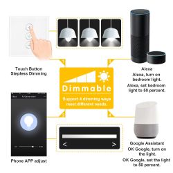
Promotional graphics:
Wiring diagram:
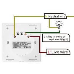
Related topics
I have already written several topics about WiFi products based on ESP (or similar chips). I mainly show the interiors there.
I also describe there the process of programming such a switch and using it with the manufacturer's app (Blitzwolf, SmartLife, Tuya, eWeLink) or Tasmota.
I recommend to read these topics, I will not repeat all the information several times and they usually apply to all such products.
List below:
- BW-LT30 i.e. WiFi adapter for bulb - test, teardown and ESP firmware upload (here with Hello World example for ESP on Arduino IDE)
- WiFi-controlled electrical socket - BW-SHP8 - commissioning and testing (based on TYWE2S module)
- Test and interior of BW-SS3, or WiFi light switch from Blitzwolf (based on TYWE3S module)
- Socket/plug with WiFi PS-16-M and eWeLink/Coolkit app - test and teardown (ESP8285 sits loose inside)
- SmartLife switch - test, interior and programming of a light switch on WiFi (similar switch, but without RF and description of programming it in Arduino via cables)
- SC3-01 SmartLife switch and ESP firmware upload via WIFI (tuya-convert/OTA) (this time programming via WiFi, no need to open the case, no soldering of cables)
- WiFi QTouch switch plugged only into L-wire - test, interior, schematic (interesting switch, which is implemented on a thyristor rather than a relay, but also has an ESP8285 inside)
- WiFi SmartLife single colour LED strip dimmer - test, interior, schematic (interesting LED strip driver on MOSFET and WB3S transistor)
- Tuya SmartSwitch WL-SW01_16 16A WiFi - test, Interior (WB2S) (slightly larger relay for higher current)
- Sonoff Basic ZBR3, the famous relay version on Zigbee. Interior, schematic (a little variety from WiFi)
- WiFi door/window sensor - test, interior, integration with other devices (sensor based on XR809/XR2 module)
- Zigbee thermometer/hygrometer with LCD TS0201 RSH-.Z-Bee-HS01 Tuya (battery-powered temperature/humidity display, this time on Zigbee)
- Interior of the TH06 clock/thermometer/hygrometer and reverse engineering of its protocol (calendar on WB3S and a bit about processing data packets in binary format via a C program)
- [/url] . Tuya SmartLife 4CH 10A quad channel WiFi relay [schematic] (slightly larger controller, unfortunately on WB3S)
- Self open source firmware for XR809 compatible with Tasmota HTTP/Home Assistant (detailed description of how to create a custom batch for the door sensor on XR809)
Additionally, a topic about Tasmota and the DIY version of the WiFi relay:
- ESP8266 and Tasmota - step-by-step WiFi relay control Additionally, I recommend a topic about Home Assistant (which can control a collection of such devices):
Home Assistant tutorial - configuration, WiFi, MQTT, Zigbee, Tasmota
Shipping, contents of the set
I placed the order on 24-07, the package was advised (did not fit in the box) on 10-08. The parcel was sent from Belgium.
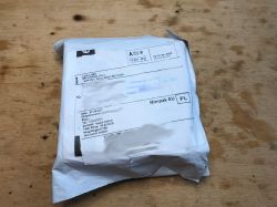
The switch is in the box, only slightly protected from damage:
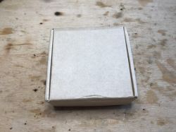
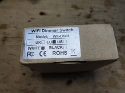
 Product model: WF-DS01
 Set contents:
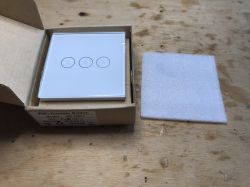
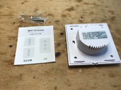
Instructions:
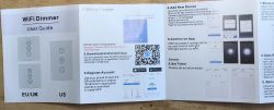

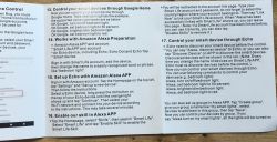 Tasmota support In topics in this series, I have often checked whether a product supports Tasmota, which is an alternative, open-source firmware for ESP and modules based on it.
Here I don't even have to check that, because the WF-DS01 is proudly listed as supported and there is even a Tasmota template prepared for it:
https://templates.blakadder.com/WF-DS01.html
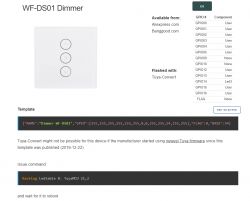
Template:
Code: text
Additionally, it requires commands to be entered:
Backlog Ledtable 0; TuyaMCU 21.2 It should work. If anyone has any problems with it, please ask, I'll try to help. In the meantime, I'm already moving on to looking at the interior.
The TuyaMCU command here comes from the fact that there are essentially two microcontrollers inside this switch - one is the ESP, responsible for communication over WiFi, and the other handles the inputs and outputs (here: dimming) and communicates with the ESP via UART using a special Tuya protocol, which Tasmota fortunately already supports.
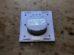
Interior of the WF-DS01 The front panel simply snaps into place, simply lever it up with a flathead screwdriver:
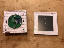
The interior consists of two boards. The board with the WiFi module (TYWE3S) is held on only two rows of goldpins (one of which is only used as a mechanical mount):
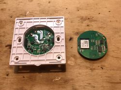
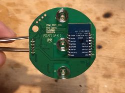
The controller board is signed YDM_WIFI_SV6 FR4 94V0 T=1.2MM 20201231.
We probably have here the version, the date of manufacture, and also the laminate type (FR4). T is probably an abbreviation for Thickness, the thickness of the board.
Now a photo from the "more interesting" side, with clear circuit markings:

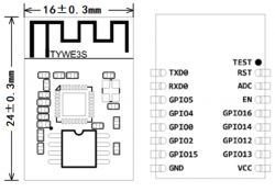
There is a TYWE3S - WiFi module from Tuya based on ESP8266, you know.
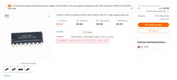
CR302 - touch button controller in SOP-16 housing (supports up to 8 buttons), rather no surprises:
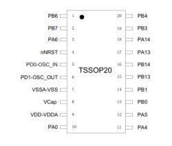
No and MM32F003 - 32-bit microcontroller based on ARM Cortex M0 core.
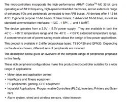
So unfortunately here we have two programmable chips, changing the ESP/TYWE3S firmware will give us full control of the switch only if we implement there support of their communication, i.e. the just mentioned TuyaMCU protocol.
The second board, the one on which the components for the mains voltage, the small flyback power supply and the triac for brightness control are located, is held by three screws inside the case.
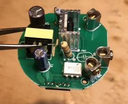
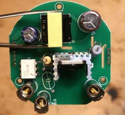
There is a place for a varistor (signed VR), the seller spared and did not put it on the board, which is a pity because its role is to protect against surges.
The white component MOC3052 in DIP-6 housing is an optotriac, it serves to control the triac:
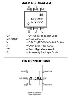

It serves to isolate the triac located on the 230V side from the low voltage side.
Well, the triac itself, on a heatsink:
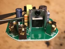
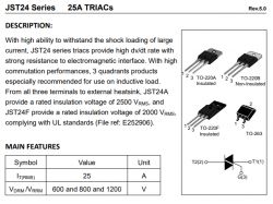
JST24B-800CW in TO-220F housing, this is a small variation, because in previous products of this type (QTouch series) I have only seen surface-mounted triacs, without an additional heatsink (although the copper spout also dissipated some heat).
Bottom of the board:
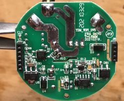
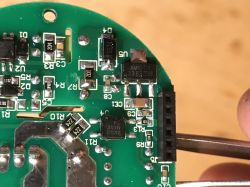
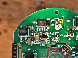
We have here primarily a simple flyback power supply realised on a DP2525 (circuit with PSR, Primary Side Regulation, feedback/reference voltage taken from the primary side, this optocoupler next to it is for another purpose):
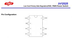
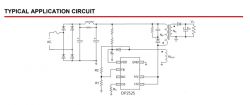
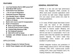 Example DP2525 application (on the board here it is slightly different, the manufacturer spared and omitted the second electrolytic capacitor and choke):
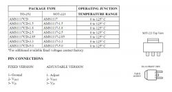
On top of that there is an LDO regulator AMS1117 3.3 providing stable 3.3V for TYWE3S:
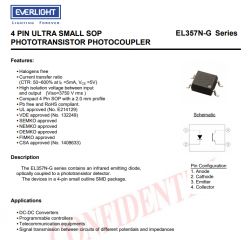
And there is an optocoupler, EL357N, connected directly to diode D3, it does not participate in the power supply of the circuit, but allows to examine the rise of the mains voltage sine wave while providing galvanic separation (needed for dimming to know when to turn on the triac):
Schema WF-DS01
I drew the schematic based on the board and the component datasheets from inside.
The component names on the schematic agree with the component names on the board, for example DB1 is Diode Bridge 1 (rectifier bridge), SCR1 is Silicon Controlled Rectifier, etc. Values similarly, I have applied the values of the surface mounted resistors to the schematic without decoding them.
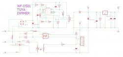
It is possible to distinguish here a pulse power supply module in flyback topology on DP2525, an executive module with a triac, and a section with an optocoupler (connected to the mains via a rectifying diode and resistors of quite high resistance), needed for the microcontroller to know when the sine wave cycle from the mains starts.
In the schematic of the low-voltage board, I have omitted the connection of the LEDs, as I considered them of little interest:
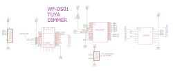
This is where we see the TYWE3S (i.e. the module with ESP) which is only responsible for WiFi communication, the MM32FF003 which handles all the functionality (triac control based on set % brightness and sine wave cycle), CR302 which handles the touch buttons and also the PA14 PA13 pins from MM32F003, which are probably used for its programming (but we do not have to program it, it is enough that the ESP batch supports the communication protocol with it).
The TYWE3S communication protocol with the MM32F003, ESP batch
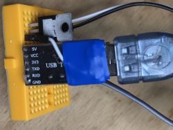
In order to eavesdrop on the communication of these two chips, I had to feed the logic board (TYWE3S and the other chips) from my own LDO chip contact board. Do not connect with the USB-UART adapter to a switch that is at mains potential.
UART adapter in 3.3V mode, connected 3.3V, ground, TX and RX:
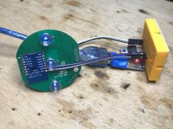
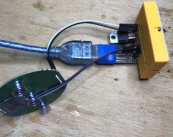
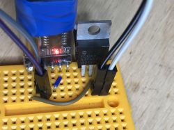 .
. 
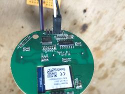
RX on TXD0 from TYWE3S.
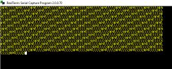
After booting and selecting Baud 9600 in the UART console I saw:
The same but already after capture, in XVI32:
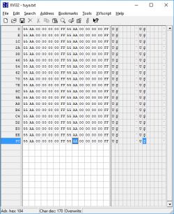
You can see the packet header and its completion (255, 0xff).
The packet appears every second. The communication is binary. This "U" is a characteristic character for the TuyaMCU protocol. In ASCI, the letter U has the code 0x55.
I dealt with a similar protocol here:
https://www.elektroda.pl/rtvforum/topic3819498.html
You can read about TuyaMCU on Tasmota's website:
https://tasmota.github.io/docs/TuyaMCU/
there are also example packets there, they too start with byte value 0x55:

Also the byte roles and packet structure are described in more detail:
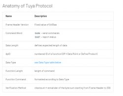
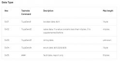
Since the protocol is known, maybe let's try to rip the batch (because I haven't paired this device with my WiFi yet, so if I rip the batch I can give it to the forum).
To rip the batch I just added the GPIO0 connection to ground and disconnected and connected the power supply (to boot the ESP with GPIO0 on ground). I downloaded via esptool.py:
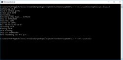
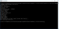 Surprisingly it went without any problems, and I thought I would have to short the RESET pin from the other microcontroller to ground or solder it (because it occupies the UART lines).
I put the batch to download below:
Short test of pairing and operation Finally, however, it falls to me to check if and how this switch works in the app. I have chosen SmartLife.
Pairing runs without any problems:
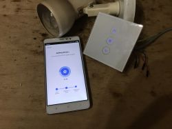
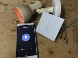

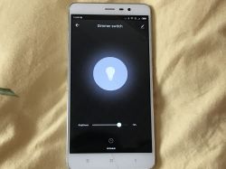
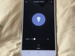
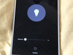
It also operates quite comfortably, but it is interesting to note that each light switch on/off (via the app and normally by touch) uses dimming/brightening animations. The light does not go out immediately, but, for example, gradually reduces until it is switched off. The manufacturer apparently thought that something like this would look attractive and modern.
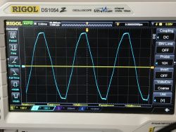
Displays of triac adjustment I think, that it is still worth illustrating to beginners how the waveforms on the input and output of such a switch look like.
On the input we have, of course, a sine wave from the mains, but on the output?
We'll see now, but first a note - any operation at mains voltage is deadly, as well as can result in damage to the oscilloscope (the oscilloscope has a common GND which is also connected to PE from the socket, so when testing the circuit we can make a short circuit).
For the tests here I used an isolation transformer.
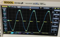
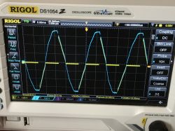
Switch off - input (channel 2) sine wave, output (channel 1) dead:
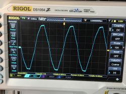
 When switched on - 100% power - two of the same waveforms superimposed on each other:
75% power:
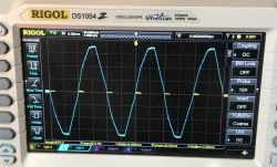
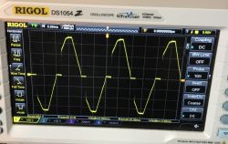
50% power:
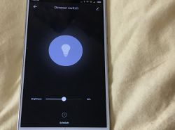
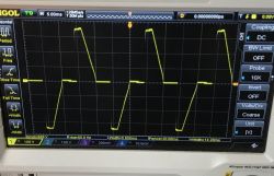
25% power:
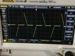
5%:
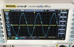
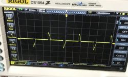 You can see very nicely how the controller "cuts" the sine wave. The MM32FF003, via the aforementioned optocoupler with diode, examines when the sine wave starts to rise, then waits a set time, and then turns on the triac. This is how it regulates the light output of the bulb.
Short performance test with Tasmota
(paragraph added later after user question) Finally I also tested this switch with Tasmota, more precisely version 9.5.0 from here:
http://ota.tasmota.com/tasmota/release/
Wireless programming has zero problems:
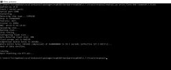
When pasting the template you have to check Activate:
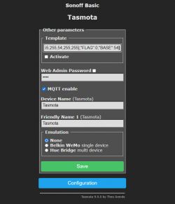
If we do something wrong, then the command will not work in the console afterwards:
Backlog Ledtable 0; TuyaMCU 21,2
It won't work, i.e. we get "Unknown command". But this doesn't mean that we have the wrong version of Tasmota, or that we have typed incorrectly, it's just that this command only works when we have Template already selected and the device type as the one with code 54 (Tuya MCU). You can check it here:
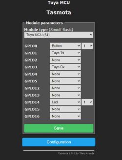
And finally Tasmota looks like this:
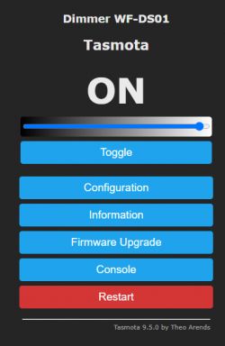
The performance of Tasmota in the video (and its responsiveness):
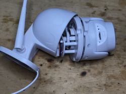
Template the next part I've already covered these switches quite a bit, so in the next part in this series I'll deal with something completely different, namely the HD WiFi camera, also from Tuya:
Summary This dimmer is a slightly better choice than its QTouch counterpart. The product from the topic is officially supported by Tasmota (we have a ready-made template for it), it is based on the TYWE3S module (this is a plus, because the QTouch has an ESP chip directly on the PCB), as well as it can be easily programmed and you don't have to desolder anything or short-circuit the RESET of the other chip to ground. And probably tuya-convert (way via WiFi/OTA) also works for it.
I don't like these extreme savings on protection, here the manufacturer didn't even mount the varistor (and there is space on the PCB for it).
Or maybe I just got one without varistor and others from this series have it?
Either way - under Tasmota and own batch it is a much better option.
There is only the question of how reliable this switch is, but I can not assess this because I just bought it, so here I will ask you - does anyone use this type of dimmer and maybe have some experience with their failure rate?
I am attaching the datasheets of the lesser known circuits from the middle and the original firmware of the switch (the curious may find them even if only to decompile it in IDA) that I ripped from it before pairing (because after pairing there is sensitive data in the ESP flash memory, including the SSID and password of the WiFi network often in plaintext).
Cool? Ranking DIY Helpful post? Buy me a coffee.


