logo elektroda
logo elektroda
X
logo elektroda
ADVERTISEMENT
Treść została przetłumaczona polish » english Zobacz oryginalną wersję tematu
  • #31 20168067
    mopplayer6
    Level 2  
    No, I sent them with audio packets but the resolution is set to 640x480 so the bezel is torn. If there is no audio package, things are easy to do.
    Understandably, you let NES linger so he can catch the timing right.
    If you share your snap code, I would appreciate your help
  • ADVERTISEMENT
  • #32 20239964
    mrzappeh
    Level 2  
    Hi, I have recently built this and have enjoyed doing so, but I seem to have an issue whenever I try to load a .rom. I have to browse the SD card to the location and then manually select, otherwise I get an error like:
    FLASH: file missing!
    KICK31SD.ROM

    No matter where I put the rom files or upper/lowercase they never seem to find them.
  • #33 20239999
    piotr_go
    DIY electronics designer
    You have to upload ROM to flash. F4 key.
    If flash was not formatted, format first.
  • #34 20240013
    mrzappeh
    Level 2  
    piotr_go wrote:
    You have to upload ROM to flash.

    Thanks, that worked.
    Is there a specific rom for 3.1SD ?
    I would like to use the SD for HD Partitions.
  • ADVERTISEMENT
  • #36 20240092
    mrzappeh
    Level 2  
    Great thanks.
    No rush, I will wait for the 1.9 specific patches.
  • #38 20240375
    mrzappeh
    Level 2  
    Thank you for the speedy upload, it is appreciated.
    A couple of questions?
    1, I am having issues with hanging when copying over files from my 3.0 or 3.1 workbench disks when the system asks for a valid workbench disk. It hangs forever and corrupts the disk on reset.
    I have noticed the Max Transfer isn't set to recommended settings, could this be the issue?

    2, I do not own a PS/2 mouse, just keyboard(pain to navigate), Is it possible to use an Amiga mouse in a DB9 port?
  • #39 20240686
    piotr_go
    DIY electronics designer
    mrzappeh wrote:
    I am having issues with hanging when copying over files from my 3.0 or 3.1 workbench disks

    Floppy -> SD ?

    mrzappeh wrote:
    Max Transfer isn't set to recommended settings, could this be the issue?

    Probably.

    mrzappeh wrote:
    Is it possible to use an Amiga mouse in a DB9 port?

    Not yet.
  • #40 20295868
    piotr_go
    DIY electronics designer
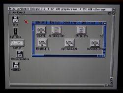
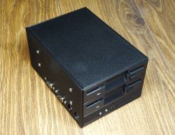
    "High density" experiments with a PC station :)
    DIY-A586 v1.9 by piotr_go

    Mikan 0.1.4 with "auto switch" function. Where you insert the first floppy after the reset will be DF0.


    DIY-A586 v1.9 by piotr_go DIY-A586 v1.9 by piotr_go
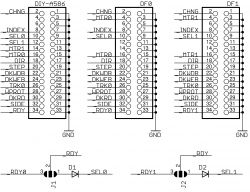
    For the switch to work properly, both stations must generate RDY.
    LEDs for stations that do not generate an RDY signal.

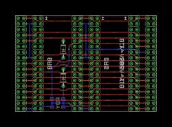
    I haven't tested the gotek yet, I'm waiting for new PCBs (from the diagram above) that have a slightly larger spacing of connectors.
    DIY-A586 v1.9 by piotr_go
  • #41 20366297
    Hetii
    Level 17  
    Hi

    @piotr_go congratulations on the next installment of the project ;)

    As a total layman in FPGA systems, I have a few questions, and I am still before the stage of blinking the diode :)
    Let's assume that I would like to run DIY-a586 on e.g. tango nano 9k, how do I know that the FPGA data is sufficient to simulate the given peripherals?
    Is every FPGA able to simulate transmission lines like HDMI or displayport i2s on its I/O ports if there are no dedicated function blocks for this purpose?
    What is the case of transferring one batch, e.g. written under XC6SLX9 to, for example, Cyclone I/II/III or others?
    What should you really be guided by when choosing a given FPGA, apart from the number of LUT elements?
    From what I checked, systems that have more than 25k logical units are usually already in BGA housings, hence my question, could it not be possible to separate functional blocks into smaller FPGAs? e.g. tango nano 9k only for graphics, and other smaller ones for the CPU and other peripherals?
    What bus should these systems be connected to make everything work properly?
  • #42 20366420
    piotr_go
    DIY electronics designer
    Hetii wrote:
    how do you know that the FPGA data is enough to simulate the given peripherals?

    Only synthesis gives 100% certainty. It's hard to tell with a complex design. With CPLD you could count.

    Hetii wrote:
    Is every FPGA able to simulate transmission lines like HDMI or displayport i2s on its I/O ports if there are no dedicated function blocks for this purpose?

    Must be serializers. Too much speed to do without them.

    Hetii wrote:
    What is the case of transferring one batch, e.g. written under XC6SLX9 to, for example, Cyclone I/II/III or others?

    You have to rewrite the blocks specific to your layout. (PLL/IO/...)

    Hetii wrote:
    What should you really be guided by when choosing a given FPGA, apart from the number of LUT elements?

    Speed, BRAM, serializers...

    Hetii wrote:
    systems that have more than 25k logical units are usually already in BGA housings, hence my question, would it not be possible to separate functional blocks into smaller FPGAs?

    Then the number of IO will become a problem, and we return to BGA :)
  • #43 20620313
    sillycon
    Level 10  
    I came across this interesting project a week ago and now I think I would like to build it. I've read the entire thread and have a few questions:
    1. After uploading the main.bin file to the flashrom, do I need to do anything else or is it enough to prepare an SD card with the Amiga ROM and it will work?
    2. When using a PC disk drive with version 1.9 of the project, do I have to convert the drive to an Amiga one?
    3. Is there a .cpl file available that can be provided when ordering boards so that the factory can solder at least some of the elements?
    4. Will version 2.0 of 020 and AGA ever be available?
  • #44 20620418
    piotr_go
    DIY electronics designer
    1. You still need to upload the Amiga core from the SD card, format the flash and load the ROMs.
    2. The PC station must be converted to an Amiga one.
    3. No.
    4. Not soon.
  • #45 20620556
    sillycon
    Level 10  
    Thank you for the quick reply. Reworking the station will be a bit of a pain, so I'd probably do it once I get the chip up and running, and there's going to be some soldering going on here. Gotek from FlashFloppy, from what I've read, is compatible with the Amiga by default, so just load FF and leave the jumper in s0?
  • ADVERTISEMENT
  • #46 20620565
    piotr_go
    DIY electronics designer
    sillycon wrote:
    Gotek from FlashFloppy, from what I've read, is compatible with the Amiga by default, so just load FF and leave the jumper in s0?

    Yes.
  • #47 20621121
    sillycon
    Level 10  
    I sat down for a while and I have an incomplete BOM in Digikey - there are no capacitors, headers and DB9M, which are astronomically priced, so you will have to look elsewhere.

    The USB port for the mouse and keyboard in DK is marked as TYPE-A - unfortunately, DK does not have such nice ones as in the picture in the project: https://github.com/piotr-go/DIY-A586/raw/master/v1.9 /img/foto_003.jpg

    My incomplete list:
    https://www.digikey.co.uk/en/mylists/list/XSJ6X819MY

    + chips and switches from ALI:
    XC6SLX9-2TQG144 - https://www.aliexpress.com/item/1005002603522383.html
    SPX1117-1.2V - https://www.aliexpress.com/item/1005004501859038.html
    MAX3232CSE - https://www.aliexpress.com/item/1005003581915749.html
    switches: https://www.aliexpress.com/item/1005005274168459.html - type 3

    Questions:
    1. As DK does not have W9825G6KH-5 in stock - will the W9825G6KH-6 memory fit https://www.aliexpress.com/item/1005005513966661.html
    2. Shouldn't 1N4148 be in SOD323 or SOD123 rather than 0603 (entered in BOM)?
    3. Ferrite bead is supposed to have some value?
    4. 15 e.g. 0603 in BOM is just 0 Ohm jumper?
    5. Headphone jack rather not from these, because I see on the PCB that it is supposed to have 5 contacts - https://www.aliexpress.com/item/1005002162553876.html

    I hope I didn't make any mistakes, I'll correct the post if necessary.
  • #48 20621134
    piotr_go
    DIY electronics designer
    sillycon wrote:
    The USB mouse and keyboard port on the DK is labeled TYPE-A

    PS/2
    https://www.lcsc.com/product-detail/Circular-...ctors_CONNFLY-Elec-DS1093-01-PN60_C77848.html

    sillycon wrote:

    wow what a price
    https://www.lcsc.com/product-detail/Programma...LDs-FPGAs_XILINX-XC6SLX9-2TQG144C_C27408.html

    1 should be OK
    2. there are also 0603 (https://www.tme.eu/pl/katalog/?search=4148%200603&s_field=accuracy&s_order=desc), but you can give something in similar dimensions
    3. for several hundred mA
    4. not populated - do not assemble
    5. https://www.lcsc.com/product-detail/Audio-Connectors_HOOYA-PJ322_C2939185.html
  • #49 20621421
    sillycon
    Level 10  
    Fantastic!
    There will even be 1N4148 at 0603 at Digikey. The search engine is a bit tricky.

    LCSC looks like a pretty good source for parts. Will take advantage for sure by ordering Spartan and other chips not available in DK. Thank you for the links.

    Ferrite bead I see that it sits in the power supply to the SD. Only now I looked at the schematic - I assume that it is supposed to have high impedance for higher frequencies and low self-resistance. Should something like this fit? https://www.digikey.co.uk/en/products/detail/murata-electronics/BLM18KG102SN1D/7798421
  • ADVERTISEMENT
  • #51 20622748
    christianmarcschaefe
    Level 1  
    Hi, I'm very interested in this DIY-A586.
    Unfortunately I'm not skilled enough to solder it on my own, though. Is there a way to buy this final assembled PCB?
  • #52 20623776
    sillycon
    Level 10  
    Instead of SPX1117-1.2V, it will probably be AMS1117-1.2. The manufacturer never seems to have a 1.2V regulator at all, see: https://www.maxlinear.com/product/power-manag...and-regulators/linear-regulators-ldos/spx1117

    The legs appear to be the same:
    https://assets.maxlinear.com/web/documents/sipex/datasheets/spx1117.pdf
    https://datasheet.lcsc.com/lcsc/2211090930_TWGMC-AMS1117-1-2_C5250987.pdf
  • #53 20623889
    piotr_go
    DIY electronics designer
    sillycon wrote:
    Instead of SPX1117-1.2V, it will probably be AMS1117-1.2. In general, it seems that the manufacturer has never had a 1.2V regulator

    Possible. I have SPX1117 in the library and I probably only changed the tip when drawing the schematic.
    On the PCB, I solder what I find first (1117 from any manufacturer).
  • #54 20627671
    sillycon
    Level 10  
    Instead of 74HCT2G125, it is better to take 74AHCT2G125DP, 125 or 74HC2G125DP, 125. It seems that at 5 V it should not matter.
  • #55 20627726
    piotr_go
    DIY electronics designer
    74AHCT2G125
    HCs are not suitable. Not these input voltage levels.
  • #56 20631296
    sillycon
    Level 10  
    at what frequency does the A586 clock the memory? I still wonder if the W9825G6KH-6 will be a good replacement:
    DIY-A586 v1.9 by piotr_go
  • #57 20631522
    piotr_go
    DIY electronics designer
    Current cores require 133MHz/CL2 max. (core PC)
  • #58 20634188
    sillycon
    Level 10  
    By the way, I took a look at Minimig, which is an open project and can also be built.

    The following observations occurred to me:
    1. Minimig seems much more complicated, 6 layers and larger PCB area,
    2. A586 v1.9 should be faster than Minimig in standard configuration; which requires a CPU (7-50MHz as standard).
    3. Minimig requires more parts and CPU on the board, but it can be accelerated with an accelerator.
    4. on A586 we have more memory 32MB vs 6MB (Minimig)
    5. The A586 has a more future-proof HDMI vs VGA output in a minute
    6. Minimig uses an older PGA which is harder to come by and more expensive if someone wanted to assemble.
    7. Bios (Winbond) in A586 allows you to program PGA without add-ons - I don't know if Minimig also has such an option(?)
    8. Minimig is already a few years old so you can count on the fact that the developers have refined the fixes during this time, does the A586 have similar compatibility?

    Generally, kudos to @piotr_go, because the hardware comparison tilts the scales in favor of the A586. I don't know what your plans are, but it would be nice to build a bigger community around the project.
  • #59 20635185
    piotr_go
    DIY electronics designer
    The original minimig was probably 2-layered. 6MB SRAM probably costs a fortune, SDRAM is much cheaper.
    Compatibility, hmmmm, at first I tried to compare with FS-UAE, I wrote a simple code displaying sprites, I adjusted DIY so that the effect was the same. Then I check the same thing on a real amiga, it works completely different!
    Blitter and CPU are not cycle compatible because they are also different between Amiga models, so I figured it doesn't make sense. 8MB CHIP... because why not :)
    It was supposed to be as fast as possible. Workbench is running briskly, so I'm happy.
  • #60 20644234
    sillycon
    Level 10  
    I went ahead and ordered parts and plates. I will try to document the whole process. if anyone is interested, they will find the project log on github, it will be my first smd project before the thicker projects that I have planned. I don't have a hot air gun so I'll try soldering. it's hard when it breaks down.

    the tiles have arrived so now it's time to plan and hence a few questions:
    1. is there any particular order in which to solder? I think back first, front later and starting with the elements in the middle, looking if I am not closing the place for the entrance of the soldering iron.
    2. what can I have soldered on the board so that I can still fasten with the programmer and program the flash? additional components sometimes interfere because they add their resistances and capacitances.
    3. Are the capacitances from the scheme https://github.com/piotr-go/DIY-A586/blob/master/v1.9/pcb/v1.9/bottom.png on the right side cast as 100nF, do you need to solder or not ? in the picture https://github.com/piotr-go/DIY-A586/raw/master/v1.9/img/foto_004.jpg the capacities are not soldered.

Topic summary

The discussion revolves around the DIY-A586 v1.9 project, a custom FPGA-based system designed to emulate various classic computers, including the Amiga and ZX Spectrum. Users share their experiences with assembly, troubleshooting, and performance issues. Key features of the board include a Spartan6 FPGA, 32MB RAM, and support for multiple configurations. Users report issues with keyboard compatibility, joystick connections, and memory speed affecting core performance. Solutions include using specific memory models (W9825G6KH-5), programming cores, and utilizing SD cards for storage. The community actively collaborates on improvements and troubleshooting, with ongoing development of cores and features.
Summary generated by the language model.
ADVERTISEMENT