Elektroda.com
Elektroda.com
X

Clock with VFD display IVL1-7/5 based on KR145IK1911 and DS32kHz

mkpoz 7059 44
This content has been translated flag-pl » flag-en View the original version here.
  • #31
    mkpoz
    Level 10  
    sundayman wrote:
    I bought a Soviet Elektronika 6.15 watch for gutting at a price lower than the display itself on Ebay. Of course, the display will be used, but if you get a used copy, it's not a problem.


    I also have my display from Soviet Electronics, I bought a broken clock for pennies on a well-known auction site ;)
  • #32
    slawekgaj3
    Level 11  
    Good day.
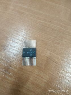
    I think that a similar integrated circuit of Soviet production, containing in its structure all (almost) elements allowing to build a clock on VFD displays, is KA1016HŁ1 ( ??1016??1 ). I made a clock on it once, it even works fine. Its shape and housing are characteristic, the Russians often produced such "inventions". In the past, such circuits were available in some electronic stores, I bought mine in Częstochowa during my studies, but it was centuries ago. I still have a few pieces...
    Clock with VFD display IVL1-7/5 based on KR145IK1911 and DS32kHz
  • #33
    szybki105
    Level 17  
    If anyone wants to risk buying a damaged Russian clock on the chip kr145ik1901 and a large VFD, it is on sale. Unfortunately, the condition of the components is unknown. The transformer is missing. Search under "Large clock display IŁCZ4-5/7 with electronics"
  • #34
    sundayman
    Level 25  
    Quote:
    he wanted to take a chance


    Well, you did. If it works, I'll have a set for 2 clocks.
    One for myself, the other for a gift.

    If only I had some more time to do it :)
  • #35
    mkpoz
    Level 10  
    I'm glad my article got so many responses :)

    And above all, he encouraged the construction of more clocks :)
  • #36
    sundayman
    Level 25  
    Quote:
    encouraged the construction of more clocks


    You could say that a friend impregnated a few people with his creation :)
    This will probably affect the market for these VFD displays.

    Seriously - if someday, someday I will find time to make this contraption, I will also boast about it, because I have a slightly different idea. But I won't tell, I won't tell.
  • #37
    jaeger
    Level 12  
    TechEkspert wrote:
    @pawelr98 what modern IC control stages would be a good bridge between a microcontroller and 30V anode voltage?


    Perhaps one of the ULN2001, ULN2002, ULN2003, ULN2004 systems will work here
  • #38
    sundayman
    Level 25  
    I got this clock from Allegro, which a friend persuaded me to buy fast105 .
    I will tell you that after disassembling I was surprised by its performance, so I will show it to you.

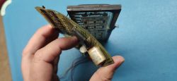
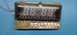
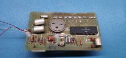
    As you can see in the pictures, it is like a normal ELECTRONIC type clock on the KP145NK1901. On the one hand, there is a PCB display with something like microswitches in the form of plates, and on the other, the rest of the components.

    But the PCB is very thin. About 0.2mm and looks like some historical "flex pcb". It is also quite flexible - it can be bent easily. But of course, without exaggeration, because as you can see, the elements are soldered normally - they are threaded and if the bend is too strong, it will probably disconnect.

    It looks funny.

    In a few places you can see traces of thermoglue - so someone has already "repaired it".
    There are 3 cut power wires coming out of the pcb. I haven't connected it yet, so I don't know if it works or not - I also need to improve the connections a bit, especially with the processor, because they don't look very special.

    Film capacitors also look like they have been lying for 100 years and a little fear to connect it. Well, if I find a moment, I'll check it, although of course I'm most interested in the state of the display.
    Clock with VFD display IVL1-7/5 based on KR145IK1911 and DS32kHz

    Clock with VFD display IVL1-7/5 based on KR145IK1911 and DS32kHz

    Clock with VFD display IVL1-7/5 based on KR145IK1911 and DS32kHz

    I have no idea why this laminate was used. The design was enclosed in a normal plastic housing, so I don't really see the justification.
    Those dire quality "micro switches" sure worked even worse because of the flexibility of the PCB.

    Was it to save the production with the laminate they had left, because it wasn't very good for anything at that time?
  • #39
    TechEkspert
    Editor
    But VFD and layout captured :) apart from the capacitors, I see 2 elements characteristic of Russian constructions,
    a piezo plate in a housing that was used in watches, electronic games and rocket launcher controllers,
    and a quartz resonator in a boat-shaped housing with a drop of tin.

    As for the name, most of the equipment was called ELECTRONICS, sometimes receivers were called ??????.
  • #40
    kris8888
    Level 38  
    The VFD probably has a broken upper filament, unless the photo is misleading.
    And the laminate, well, as befits Soviet consumer products. Cheap and whatever.
    These Soviet quartz resonators are also not the best, after years they either do not want to generate at all or show a very large aging effect (deviation from the nominal frequency).
  • #41
    Gizmoń
    Level 28  
    TechEkspert wrote:
    As for the name, most of the equipment was called ELECTRONICS, sometimes the receivers were called ??????.


    In Poland, most of the equipment was called Unitra, sometimes the receivers were called Tosca :) The Soviet "Elektronika" was a union of many plants and research centers, hence the name on many devices. However, there were a lot of names of individual products - not only Junost, but also Elektron, Foton, Meridian, Sport and a lot of others. Including the most famous Ruby :D

    And I still have a question for the author: in what program was the clock diagram drawn? It looks very "Russian"!
  • #42
    sundayman
    Level 25  
    Quote:
    broken upper filament


    Fortunately not. But for now, I still don't know if it's otherwise functional.
    Unfortunately, I have other urgent work and will have to wait a while...

    Quote:
    rocket launchers


    what rockets?? :|
  • #43
    mkpoz
    Level 10  
    Gizmoń wrote:
    And I still have a question for the author: in what program was the clock diagram drawn? It looks very "Russian"!


    The original schematic is from a Russian electronics forum. It was modernized by me and adapted to my project. That's why it looks "Russian" ? I think that the diagram perfectly reflects the spirit of the project ?

    Added after 2 [minutes]:

    sundayman wrote:

    Quote:
    rocket launchers


    what rockets?? :|


    Well, probably obvious buddy ? such for carrying baubles from "A" to "N" ?
  • #44
    szeryf3
    Level 27  
    @sundayman however you were tempted to buy.
    The clock looks a bit tired of life, but I hope that the VFD will be functional because this element is the most valuable of it.
    When you finish resuscitating this clock, praise it.
  • #45
    sundayman
    Level 25  
    Quote:
    such for carrying baubles from "A" to "N"


    do you have any connection with this topic? Because I'd love to buy a few :)

    Today I got a package with layouts from a German.
    They look unused. In one, these paths in the "windows" can be seen very well, in the other worse - in some places they are covered with a thin layer of plastic.
    The form seemed to be getting worse.

    But overall both layouts look good.