 .
.
Here I will show how additional devices can be controlled from a three-button WiFi switch. For this I will use Tasmota and OpenBeken . The mechanism will work completely serverless, as Groups from Tasmota communicate directly with each other over UDP via broadcast/multicast. I will connect an LED strip and a socket with energy measurement to the free slots of the switch. The end result of the work will be a switch with three touch buttons, the first one controlling the ceiling lamp (as usual) and the second and third ones controlling any device we support with DGR (e.g. an LED strip, or another switch, or a smart plug, or an LED lamp...).
Related topic .
Today's topic is somewhat of an extension of what I showed 2 months ago:
Tasmota Device Groups - merging OpenBeken (BK7231T/BK7231N) with Tasmota .
The main difference is that then I was only assigning one group to each device, whereas here we will have one switch controlling two groups (with myself counting - even three).
Preparing the switch .
I had a single switch in the box from the room, both the phase and neutral wires were connected there.
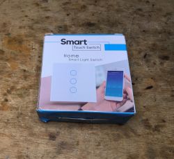
For this reason, I have decided to buy a triple switch, as this will allow me to use its other two buttons freely:
 .
.
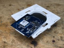
The switch ended up on an ESP8266 (TYWE3S);
 .
.
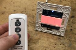
I bought a version of it with RF433, here's a test with the remote:
How to pair the RF remote? We simply press a button on the (aftermarket) switch for longer and then press a button on the RF remote control, done. Often there will then be beeps from the buzzer - one beep means we are pairing, two beeps means the code has been memorised.
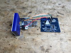
I did the Tasmota upload according to the topics:
SmartLife switch - test, interior and light switch programming on WiFi .
ESP8266 and Tasmota - step by step WiFi relay control
Really, just the power supply, RX, TX and IO0 to ground. I didn't have to connect anything else.
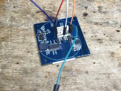 .
.
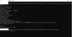
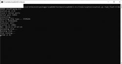 .
.
I also made a backup of the batch.
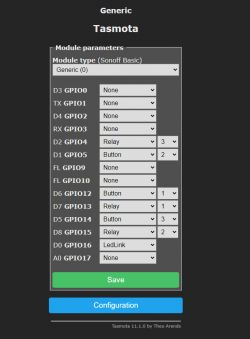
Here is a breakdown of the connections:
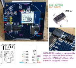 .
.
Tasmota configuration:
 .
.
Remove/disconnect unnecessary relays .
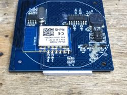
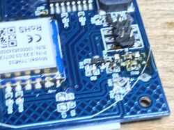
In the situation described here, I only need one relay in the box - the other two are redundant, as they are really just 'transmitters' of Tasmota Device Groups packets. Consequently, I can cut these two relays off from their control by soldering out their transistors:
 .
.
This will save some energy.
Configuring the device to be controlled using the OpenBeken LED strip as an example .
The device we will control must support the Tasmota Device Groups protocol. OpenBeken already supports it, what's more it can be configured via the GUI (and not with commands, like Tasmota), so I decided to use it.
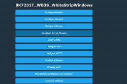
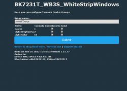
In Options->Device Groups we enter the group name and select what we are sending/receiving.
 .
.
 .
.
For this example, all we need to do is pick up the Power state.
Configure the switch-controller .
Now we need to start Device Groups on the switch and pair its relay 2 and 3 with individual devices.
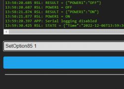
We enable the device groups - SetOption85 1:
 .
.
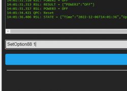
We enable the linking of device groups separately with relays - SetOption88 1:
 .
.
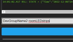
We set the second group (for relay 2) to the group name of my LED bar DevGroupName2 [name]:
 .
.
From this point on, changing the state of this switch (relay 2, via WiFi, or pressing a button, or via RF433) also changes the state of my LED strip:
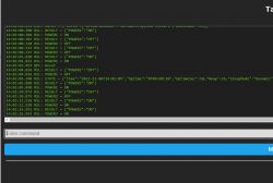 .
.
The state of the LED bar changes and its logs show that it is receiving DGR packets:
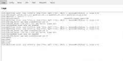 .
.
The next device we pair similarly - only that we enter index 3 and not 2. .
It is worth remembering that you can assign something to the group in which "our" relay is - and then, for example, two light switches will work together.
I have also connected a smart socket to this switch in this way.
Summary .
This use of the two free touch buttons on the aftermarket switch is really very convenient. It gives us convenient control over a variety of devices, including those that would normally require an app or have a switch in an inconvenient location - for example, like an LED strip from a light above a window.
The whole system works without any server, so all we need to do is buy two devices of any kind, upload Tasmota (or OpenBeken) and we can combine them into groups.
It is worth adding here that groups work "both ways", so we can even have a second switch configured also for these 2 (or thereabouts 3) groups and their states will synchronise together.
A change in the state of the first switch will be reflected on the second switch, and vice versa.
Several devices can belong to one group, not just two.
The additional RF remote makes the project even more attractive, because essentially this use of a switch with RF allows us to pair the RF remote with any Tasmota/Obk IoT device that would not normally support the RF remote . For example, I haven't seen LED strips much with an RF remote, and with the treatment from the topic I can control my LED strip via this RF remote.
A very convenient solution - both the switch and the remote control. I don't like to use my phone for IoT myself (maybe the younger ones like to walk around with their phone all the time, but it's not for me) and RF remote controls and after-button switches with extra buttons seriously make it easier for me to operate in a 'smart' home.
PS: in the next part I will show how such a switch can be better scripted, already with OpenBeken, we will handle single and double click separately and we will connect more devices... .
Cool? Ranking DIY Helpful post? Buy me a coffee.


