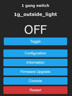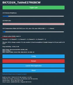
Hello, I'll show you how to make simple connections and automations between devices with Tasmota and OpenBeken (BK7231T / BK7231N / XR809 / T34 / BL602 / W600 / W601 / W800 / W801).
Tasmota Device Groups, also known as DGR, is a protocol for connecting IoT devices to Tasmota's software into groups without the use of an external server - communication takes place directly between devices via multicast / broadcast UDP. DGR allows not only to combine devices into mentioned groups; it also allows you to control groups of, for example, LED lamps from the single switch (this allows you to eliminate the known problem called "switching off the switch from the chandelier cuts off the power and WiFi light bulb, so that they cannot be separately controlled from HA"), but more on that later.
Here I will show two simple examples (in several versions).
DGR assumes that the devices are in single LAN.
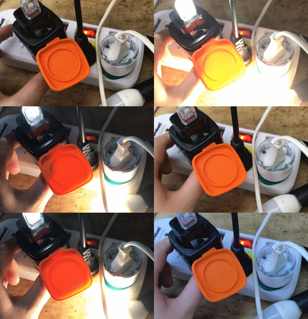
(the title gif shows the operation of DGR in action; there are two 'smart plugs'; the user switches the state of one, orange here, and the other follows - it also turns off and switches)
Device Groups documentation from Tasmota
Device Groups primarily requires a group name - the group name is textual, such as "mySockets1".
In addition, each device is set with flags that define what that device will transmit (when the state changes) and what it will receive (when the state of another device in the group changes).
For example, we can do so that one switch transmits its power state, and others only receive this state. We can also both transmit and receive the power state.
The same logic applies to LED color, brightness and temperature - with both send and receive options configurable.
On Tasmota, DGR is activated by the command:
SetOption85 1
On Tasmota, the group name is set by the command:
DevGroupName testSocket
On Tasmota, the sending and receiving flags are determined by the command:
DevGroupShare 1,1
Flag values:
| Flag | Role |
| 1 | Power |
| 2 | Light brightness |
| 4 | Light fade / speed |
| 8 | Light scheme |
| 16 | Light color |
| 32 | Dimmer settings (presets) |
| 64 | Event |
Flags are bit flags, i.e. we combine them by adding, e.g. flag 1 and 2 together give 3.
You will find everything here:
https://tasmota.github.io/docs/Device-Groups/#operation
In OBK, however, everything is on the GUI - no commands for beginners .
Example 1 - Smart Sockets - BW-SHP6 (ESP8266 - Tasmota) and Mycket PE01-E (BK7231N)
We have two sockets, one on ESP8266 and one on Beken:
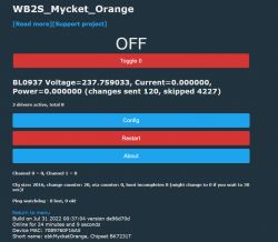
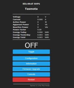
We will now configure these two sockets so that the state change of one reflects the state of the other.
We want to share the POWER state - flag 1.
The group name will be "testSocket".
Tasmota configuration - command to be executed:
BackLog SetOption85 1; DevGroupName testSocket; DevGroupShare 1,1
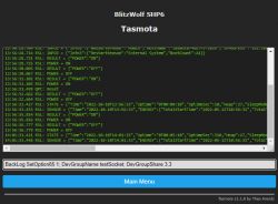
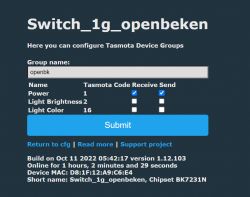
OpenBeken configuration - we only need to click in the GUI (Options-> Configure Device Groups):
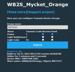
In fact, that's it - from now on, any change in the state of one device will result in a change in the state of the other device (both the MQTT and the button on the housing, as well as clicking on the WWW panel).
Demonstration:

Example 2 - single color LED strips - one on ESP8266, the other on WB3S
Here are the heroes of this demonstration:
- WiFi SmartLife single-color LED strip dimmer - test, teardown, diagram
- WiFi LED strip dimmer 5V-28V - teardown, Tasmota, Home Assistant
The configuration is similar to the previous one, but this time in DevGroupShare we also attach the strip brightness flag.
Here is the Tasmota configuration:
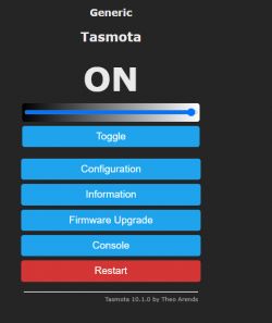
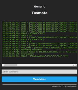
And this is the OpenBeken configuration:
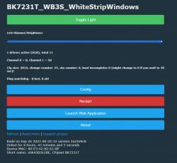
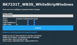
Results: both strips are changing their states together, both power and brightness.
DGR scripting
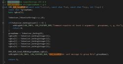
In OpenBeken we have script commands that allow you to operate "from the outside" on Tasmota Device Groups. They only require the initial, one-time start of DGR via "startDriver DGR" in the console.
The command to change the brightness:
DGR_SendBrightness stringGroupName integerBrightness
Command to change the power state:
DGR_SendPower stringGroupName integerChannelValues integerChannelsCount
integerChannelValues is a decimal record of the values of channels (relays), eg for 4 relays where numbers 1 and 3 are turned on we write their states as bit 0101 or decimal 5. Count is the number of relays, here 4, in this example. For LED lamps it is always 1.
We create longer scripts in OBK by creating the "autoexec.bat" file on the computer and transferring it to the Vue / JS web panel in LittleFS, here:
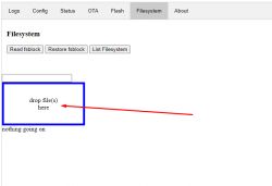
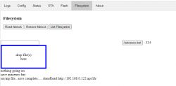
Remember that OTA cleans this sector (quite an unfortunate system, but developed by one of the contributors, motivated by a potential increase in LittleFS sector size for more advanced applications), so you should have a copy of the files or use "save fsblock" to save it and "read" to recover.
If we type commands into the console but don't pass them to autoexec, the device will forget to execute them after rebooting.
Example 3 - DGR scripting - control of two stripes with one switch
Even more can be done with DGR. We will take an unused switch with two buttons:
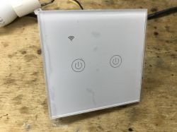
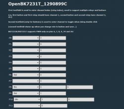
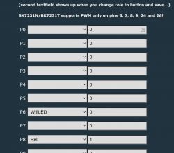
We already know its configuration - the buttons are on pins 8 and 10. Let's write an event for it - these events are per-pin, 8 and 10 are the pin indexes:
startDriver DGR
addEventHandler OnClick 8 DGR_SendBrightness roomLEDstrips 0
addEventHandler OnClick 10 DGR_SendBrightness roomLEDstrips 255
From now on, one button turns on all the LEDs, and the other turns them off.
(Dimmer values are from 0 to 255 in Tasmota)
Example 4 - DGR scripting - control of two stripes with one switch - v2
Only On / Off is not enough? You can get more.
We will use channel 4 (which is what I chose at random) as a variable and add a stepwise brightness control.
startDriver DGR
addEventHandler OnClick 8 backlog setChannel 4 0; DGR_SendBrightness roomLEDstrips $CH4
addEventHandler OnClick 10 backlog setChannel 4 255; DGR_SendBrightness roomLEDstrips $CH4
addEventHandler OnHold 8 backlog addChannel 4 10 0 255; DGR_SendBrightness roomLEDstrips $CH4
addEventHandler OnHold 10 backlog addChannel 4 -10 0 255; DGR_SendBrightness roomLEDstrips $CH4
Now pressing the button gradually decreases / increases the brightness, and clicking it immediately turns off / on the stripes.
the backlog is needed to be able to execute several commands at once.
On the other hand addChannel 4 10 0 255 adds a value of 10 to channel 4, while 0 and 255 are the maximum and minimum value of this channel (so-called 'clamp'), values greater than 255 are set to 255 and less than 0 to 0 ...
But you can go one step further ...
Example 5 - DGR scripting - control of two stripes with one switch - v3
The previous example still did not allow you to conveniently control the brightness from the switch GUI. This can also be fixed.
New script:
startDriver DGR
setChannelType 4 dimmer256
addEventHandler OnChannelChange 4 DGR_SendBrightness roomLEDstrips $CH4
addEventHandler OnClick 8 backlog setChannel 4 0
addEventHandler OnClick 10 backlog setChannel 4 255
addEventHandler OnHold 8 backlog and channel 4 10 0 255
addEventHandler OnHold 10 backlog addChannel 4 -10 0 255
SetChannelType 4 Dimmer256 will make the bar appear:
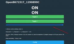
The OnChannelChange event, on the other hand, will cause each change of channel 4 to send its new value to the DGR. Also one with GUI. So we can control all LEDs with one web panel.
NOTE: If we send a new channel 4 value via MQTT, it will also be transferred to DGR.
Example 6 - off timer
This is still a small bonus.
We will add a timer that turns off the lights after the set time.
Let's say it will be on channel 5.
We will set its value with a bar.
setChannelType 5 dimmer256
addRepeatingEvent 1 -1 addChannel 5 -1 0 10000
addChangeHandler Channel5 == 0 setChannel 4 0
We add this to the previous configuration.
From now on, the second bar is the time in seconds - you can also change it to minutes (we change addRepeatingEvent 1 to 60 - an event every 60 seconds instead of one) - after this time the lights turn off.
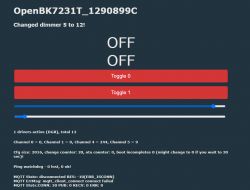
It is a bit lacking to sign what's what - it will be added soon.
The method with the ghost device
It is also worth noting that both in Tasmota and in OpenBeken there is also a method of controlling the DGR group through a device - "dummy" / "ghost".
For example, if we want to control 3 single-color LED strips and we have a two-button switch, we can configure this switch so that OpenBeken "thinks" that it is also an LED strip (set its PWM pin, etc.) and operate on its channels without scripting " DGR_SendBrightness ", while set mu in Options-> Configure Device Groups group and flags.
It is important to remember that there are two ways - we can either use automatic DGR (the mentioned Options-> Configure Device Groups), or "manually" send packets via scripts (DGR_SendBrightness command etc).
Summary
OpenBeken is very easy to connect to Tasmota - even without Home Assistant. In OpenBeken, configuring DGR is even simpler, as the basics are available on the GUI itself, in Options-> Configure Device Groups. More advanced things are also possible through simple event mechanisms. More advanced scripts will also be available soon.
This was the first part about Tasmota Devices Groups - in the second I will test groups with RGB and RGBCW 'bulbs'.
NOTE: The functionality is at the testing stage - any bug reports from BK users are welcome!
Cool? Ranking DIY Helpful post? Buy me a coffee.


