logo elektroda
logo elektroda
X
logo elektroda

[BK7231N/CBU] Door sensor without TuyaMCU - how to connect to UART RX/TX

gramais 10290 61
ADVERTISEMENT
  • ADVERTISEMENT
  • #32 20671923
    taggbricka
    Level 7  

    >>20638363
    Quote:


    P16 DoorSnsrWSleep_nPup
    P20 Btn
    P23 BAT_ADC
    P26 WifiLED


    Add P17 to make battery voltage work

    P16 DoorSnsrWSleep_nPup
    P17 BAT_Relay <------------------
    P20 Btn
    P23 BAT_ADC
    P26 WifiLED
  • #33 20672102
    p.kaczmarek2
    Moderator Smart Home
    Generic sleep can be adjusted with DSTime command. It must be run from autoexec.bat on startup. This will work if you have already started DoorSensor driver.
    Helpful post? Buy me a coffee.
  • #34 20684007
    auntlydia
    Level 10  

    >>20671923

    Thanks!!
    With these settings, it works well, but I figured we have to set a different channel for the battery functions - one channel, and for the other functions - one channel. If all have the same channel, the device keeps restarting and does not work properly.
  • #35 20690893
    simovicsava
    Level 7  

    Hello everyone,

    I've been gone for a long time, but better late than never. :-)

    These settings are the only ones that work, and the sensor goes into a deep sleep, so it doesn't eat up the batteries in 10 hours.

    16 DoorSnsrWSleep_nPup 1
    17 BAT_Relay 1
    20 Btn 2
    23 BAT_ADC 1
    26 WifiLED_n 0

    It just annoyed me that the status of the sensor was always reversed.
    When the sensor was open, it indicated that it was closed, and when the sensor was closed, it indicated that it was open.
    I tried all possible pin settings, especially P16 DoorSnsrWSleep / DoorSnsrWSleep_pd.

    The only one that works stably, but with an inverted status is 16 DoorSnsrWSleep_nPup 0

    So I decided to solve it in another way.

    I just added the following code to configuration.yaml :

    binary_sensor:
    - platform: template
    sensors:
    virtual_binary_sensor_1:
    friendly_name: "Virtual Window Sensor 1"
    unique_id: "Virtual_Window_1"
    device_class: window
    value_template: "{{ 'on' if is_state('binary_sensor.sensor_1_0', 'off') else 'off' }}"

    I have created a virtual binary_sensor, which inverts the state of the physical sensor

    Physical sensor is "binary_sensor.sensor_1_0"

    and the virtual binary_sensor that is thus recognized in the system is "virtual_binary_sensor_1"

    I use:
    Chipset: BK7231N
    Version: 1.17.211

    I hope I was of help.
  • #36 20690964
    auntlydia
    Level 10  

    Hi,

    For me, it works too with the following settings:

    16 DoorSnsrWSleep 0
    17 BAT_Relay 1
    20 Btn 0
    23 BAT_ADC 1
    26 WifiLED_n 0

    It seemed to be important that battery settings are on another channel than the sensor/LED/btn.

    Also, I added 'backlog dstime 30' as a startup command, so the sensor puts itself into deep sleep after 30 seconds from the last state change and only wakes up when the door is opened/closed. With all these settings, there is no battery drain for me, and it works perfectly until now.

    Thanks for the YAML, it's a smart solution! I will try it and see if it works better for me than my current workaround, which I also like to share here:

    - Create a helper toggle, here I use the name "Door State Helper" --> input_boolean.door_state_helper
    (Choose a nice icon that suits the sensor's purpose)
    - Here, my entity of the sensor has the name "binary_sensor.dw00_0"
    - Create an automation with the following settings:

    2 Triggers:

    platform: state
    entity_id:
      - binary_sensor.dw00_0
    to: "off"
    id: door_open
    from: null


    and:

    platform: state
    entity_id:
      - binary_sensor.dw00_0
    to: "on"
    id: door_closed
    from: null


    Actions:

    choose:
      - conditions:
          - condition: trigger
            id: door_open
        sequence:
          - service: input_boolean.turn_on
            data: {}
            target:
              entity_id: input_boolean.door_state_helper
      - conditions:
          - condition: trigger
            id: door_closed
        sequence:
          - service: input_boolean.turn_off
            data: {}
            target:
              entity_id: input_boolean.door_state_helper
      - conditions:
          - condition: state
            entity_id: binary_sensor.dw00_0
            state: unavailable
        sequence:
          - service: input_boolean.turn_off
            data: {}
            target:
              entity_id: input_boolean.door_state_helper


    - Finally, create a simple button card to observe the state of the sensor by icon color change (blue/yellow)

    show_name: true
    show_icon: true
    type: button
    tap_action:
      action: none
    show_state: false
    entity: input_boolean.door_state_helper
    hold_action:
      action: none
    name: Door Open?
    icon_height: 100px


    I am still waiting for the firmware to be updated with an inverted sensor setting as a flag, as p.kaczmarek2 suggested this idea in my other post. But even without such a setting, we can always find a way in HA to invert stuff.

    I also found another approach to invert the sensor already in OpenBK so the state is sent correctly to HA:
    - In module configuration, for pin 16, instead of "DoorSnsrWSleep", we can use "dinput_n" role
    - Now we have to enter the startup command:

    backlog startDriver DoorSensor; dstime 30


    - The dstime command is by choice, the standard sleeping time for the door sensor is 60 seconds
    - If you now set the sensor to show as "Door" in HA, it shows the open/closed state correctly
    - Drawback: once the 60 seconds countdown starts in OpenBK, it counts down to 0 and then puts the device to sleep regardless of further state changes. But it wakes up again when the state changes, so it should serve functionality for standard scenarios in daily life

    Now we have lots of options to play around with!
  • #37 20690989
    p.kaczmarek2
    Moderator Smart Home
    I didn't have time to test it, but I pushed option to swap the door state, just set the flag and "open" and "closed" options are reversed:
    Screenshot of a user interface showing configuration flag options with the highlighted option Flag 42 - [DoorSensor] Invert state.
    Please try it out and let me know if it works
    Helpful post? Buy me a coffee.
  • #38 20690995
    auntlydia
    Level 10  

    Hi, thanks! But where do I find this option? In the newest firmware release 1.17.211, it does not appear.
  • ADVERTISEMENT
  • #39 20691088
    p.kaczmarek2
    Moderator Smart Home
    Helpful post? Buy me a coffee.
  • #40 20691104
    auntlydia
    Level 10  

    Awesome! It works perfectly! Thanks so much, problem solved. =)
  • #41 20691495
    simovicsava
    Level 7  

    Super! It works perfectly! Thanks so much, problem solved :-)))
  • #42 20691642
    p.kaczmarek2
    Moderator Smart Home
    I've decided to choose a flag and not a new pin roles, because with all the options (no pull up, pull up, pull down) I would have to add 3 more roles and that's a lot.... I hope that flag will be easier to use than that.
    Helpful post? Buy me a coffee.
  • #43 20733838
    calomx
    Level 4  

    Anybody can help me to identify pins to simulate open/close instead of a magnetic bar? Thanks.
  • #44 20733922
    p.kaczmarek2
    Moderator Smart Home
    Have you tried to do Tuya config extraction?
    It can be done two ways:
    - via BK7231 flasher, if you read 2MB backup
    - via already flashed OBK, that way: https://www.youtube.com/watch?v=WunlqIMAdgw
    Helpful post? Buy me a coffee.
  • #45 20734226
    calomx
    Level 4  
    Hello. I think I didn't explain well what I intended. The idea was to physically replace the magnet that operates the opening and closing with a physical switch. So what I needed was to know the pins where the reed is located, which changes its state as you approach the magnet.

    Added after 6 [minutes]:

    I tried this.. works but drain battery!

    Electronic circuit board with visible traces, components, and soldered wires.
  • ADVERTISEMENT
  • #46 20734572
    auntlydia
    Level 10  
    Hi, not sure if I understand your concern correctly, but the pin for the door sensor (magnet recognition) is pin No. 16 (P16) in OpenBK in my device.

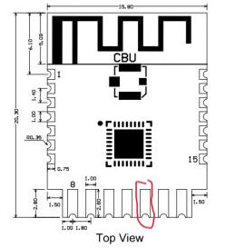
    As we have the pinout description of CBU module at the beginning of this topic here, internal IC pin No. 16 points towards pin No. 12 of the CBU module:

    Screenshot of a table showing pin configuration in the CBU module, where pin 12 is labeled as P24 and supports hardware PWM.

    so, counting the pins following the numbers, we should arrive on pin next to GND:

    Diagram of CBU module with highlighted pin.

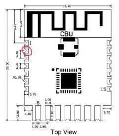
    but I am a little confused about the numbering, we have 3 columns, "Pin Number", "Symbol", "I/O Type". So, if in OpenBK the "P16" refers to "Symbol", then it points towards CBU pin No. 2!

    Screenshot of a table showing pin number 2, symbol P16, type I/O, and description as common GPIO which can be used as SPI_MOSI, corresponding to pin 12 of the IC.

    Technical drawing of a CBU module with a pin highlighted.

    maybe you can try both and see if you get the result you are hoping for!
  • ADVERTISEMENT
  • #47 20734581
    calomx
    Level 4  
    I need to identify red pins... I can't see any red visible ;)
  • #48 20734584
    p.kaczmarek2
    Moderator Smart Home
    On your board, H1 is the Hall sensor, this method is used to determine whether door is open or closed.
    Helpful post? Buy me a coffee.
  • #49 20734586
    auntlydia
    Level 10  
    I think if you use a multimeter to follow the traces of the pins that I suggested, you would probably arrive at the points that react on the magnet... another option would be, to use the button as physical switch or replace the button with the switch you prefer..!?
  • #50 20734595
    calomx
    Level 4  
    auntlydia wrote:
    I think if you use a multimeter to follow the traces of the pins that I suggested, you would probably arrive at the points that react on the magnet... another option would be, to use the button as physical switch or replace the button with the switch you prefer..!?


    But don't have any button. Weird for me is I can't see any reed as I can see on others door sensors.
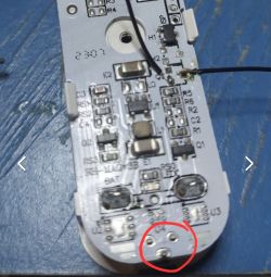
    If I put a switch on H1 pins (like my picture with wires) I can simulate open/close door but drains battery in one day when it's on close state!

    Thanks
  • #51 20734609
    auntlydia
    Level 10  

    Close-up of a circuit board with various electronic components and soldered wires, with an element marked in red.

    We should have a button here on the other side, no?

    I think it is also possible to use other unused pins of the CBU module to connect more sensors / buttons / switches to, but I have never tried it. However, I remember having seen a video where p.kaszmarek2 (?) soldered an IR receiver to an unused pin of the module that holds the BK7231 chip and made it work 😁
  • #52 20734616
    calomx
    Level 4  

    auntlydia wrote:
    Close-up of a circuit board with various electronic components and soldered wires, with an element marked in red.

    We should have a button here on the other side, no?

    Yes, sure, but this button is for reset... not to simulate open/close :)

  • #53 20734629
    p.kaczmarek2
    Moderator Smart Home
    calomx wrote:
    Weird for me is I can't see any reed as I can se on others door sensors.

    As stated above, there is no reed in this door sensor. Some other sensors are reed-based, but this one is based on hall sensor.


    calomx wrote:

    If I put a switch on H1 pins (like my picture with wires) I can simulate open/cose door but drains battery in one day when its on close state!

    H1 is a hall sensor, it is used to detect whether door is open or closed. You can replace it with any other kind of sensor you want, also with a mechanical button. You can also connect mechanical button to any other GPIO of BK7231 and just configure it in the firmware to suit your needs.

    calomx wrote:

    but drains battery in one day when its on close state!

    Even the factory version of this device requires the deep sleep usage, which is already well supported by OpenBeken. Have you configured your device to use deep sleep?
    Helpful post? Buy me a coffee.
  • #54 20734644
    calomx
    Level 4  

    calomx wrote:

    but drains battery in one day when it's in the closed state!

    Even the factory version of this device requires the deep sleep usage, which is already well supported by OpenBeken. Have you configured your device to use deep sleep?


    If I use the sensor normally with a magnet, there is no drain.
  • #56 20734672
    calomx
    Level 4  

    p.kaczmarek2 wrote:
    Are you using OBK or Tuya firmware?


    Tuya
  • #57 20734700
    p.kaczmarek2
    Moderator Smart Home
    Hmm, if that's the case, I'd start with attaching UART to TX2 to see if your modified sensor goes into the sleep mode with Tuya firmware or not. Maybe you need a different electrical connection.

    I think we had a schematic drawn for that one somewhere but I can't find where.
    Helpful post? Buy me a coffee.
  • #58 20816323
    atomphil
    Level 10  
    Thanks to this topic here, I was also able to successfully flash my Wifi door sensor with OBK.

    However, it shows a strange behaviour: When I place or remove the magnet in front of it, the status of channel 0 only changes for a short time from 1 to 0, only to jump back to 1 immediately afterwards.

    You can see this clearly in the HA log.

    How can I integrate the sensor as a door contact (open/closed) and without this voltage in HA?


    Here is my config:
    {
      "vendor": "Tuya",
      "bDetailed": "0",
      "name": "Full Device Name Here",
      "model": "enter short model name here",
      "chip": "BK7231N",
      "board": "TODO",
      "flags": "3072",
      "keywords": [
        "TODO",
        "TODO",
        "TODO"
      ],
      "pins": {
        "16": "DoorSnsrWSleep;0",
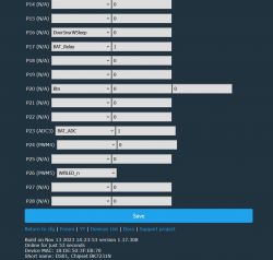
        "17": "BAT_Relay;1",
        "20": "Btn;0",
        "23": "BAT_ADC;1",
        "26": "WifiLED_n;0"
      },
      "command": "backlog dstime 30",
      "image": "https://obrazki.elektroda.pl/YOUR_IMAGE.jpg",
      "wiki": "https://www.elektroda.com/rtvforum/topic_YOUR_TOPIC.html"
    }
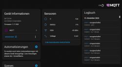
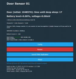

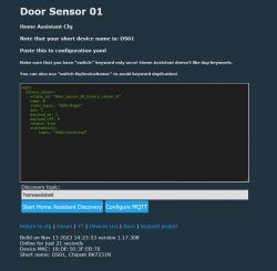
    View of the user interface for managing the BK7231N sensor. Screenshot of a door sensor interface showing connection status, battery level, and other technical data. Device configuration page with various pin settings and states. Screenshot of door sensor configuration in Home Assistant
  • #59 20816855
    auntlydia
    Level 10  

    I have set the channel type "OpenClosed" for channel 0 via the web application. So it shows the status correctly in firmware, closed with magnet and open without magnet. But for this, flag 42 needs to be checked. Also make sure to put the magnet in the correct position. It occurred to me that if the magnet is too close, it won't be recognized. If you use the original magnet that came with the sensor and place it centrally around 1 cm from the sensor, it should be stable. If you still have trouble with the magnet, maybe it's worth trying with the original Tuya firmware and see if you have the same problem, then it could be hardware related. If you don't want the battery voltage, just set the BAT_ADC and BAT_Relay pins back to blank, and reboot.

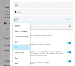
    In HA, you can then choose the "Door" option in the entity config, and it will give you a nice icon and looks great, I think =)

    Screenshot of a web app showing device configuration and setting the icon to Door.
  • #60 20817009
    atomphil
    Level 10  

    auntlydia wrote:
    Also make sure to put the magnet in the correct position. It occurred to me that if the magnet is too close, it won't be recognized. If you use the original magnet that came with the sensor and place it centrally around 1 cm from the sensor, it should be stable.


    That's the solution! Thank you very much.

Topic summary

The discussion revolves around connecting and configuring a Tuya door and window sensor equipped with a BK7231N chip without using TuyaMCU. Users seek guidance on accessing the RX/TX pins for flashing firmware and configuring the device for MQTT/Home Assistant integration. Various solutions are proposed, including using specific pin configurations for the door sensor and button, adjusting baud rates for flashing, and troubleshooting issues related to firmware and battery drain. The conversation also covers the importance of deep sleep mode for battery conservation and the need for correct pin assignments to ensure proper sensor functionality. Users share their experiences with different configurations, including inverting sensor states and adjusting sleep settings to optimize performance.
Summary generated by the language model.
ADVERTISEMENT