Elektroda.com
Elektroda.com
X

GPT-4: Discover the Power of ElektrodaBot, the Revolutionary Bot Driven by ChatGPT-4

gulson 1530 40
  • GPT-4: Discover the Power of ElektrodaBot, the Revolutionary Bot Driven by ChatGPT-4
    Exciting news! We have recently upgraded our AI system to the latest and most advanced version yet - GPT-4.0. As one of the select few with access to this cutting-edge technology, we are thrilled to offer you the opportunity to test it out for free!

    Our previous version, ElektrodaBot, although helpful, occasionally provided misleading answers due to its limited knowledge base. However, with GPT-4.0, we are confident that you will be amazed by the accuracy of its responses.

    Have a question about electronics? Simply call ElektrodaBot and let GPT-4.0 do the rest! Don't miss out on this opportunity to experience the future of AI technology firsthand. Test out GPT-4.0 today and discover the difference for yourself!

    Let's move on to the mistakes compared to 3.5 model. In response to my first question about the value of a ceramic capacitor "103", the GPT-3 model ultimately answered correctly, but during the calculations, it wrote: the capacitance of this capacitor is 10^3 pF, which is 10000 pF or 10 nF.
    And it should be 10^4 pF or 10*10^3 pF.

    Let's check it now.
    @ElektrodaBot I have a ceramic capacitor with "103" written on it, what is the capacitance of this capacitor?

    Cool? Ranking DIY
    About Author
    gulson
    System Administrator
    Offline 
    gulson wrote 23464 posts with rating 3246, helped 75 times. Live in city Kielce. Been with us since 2001 year.
  • #2
    ElektrodaBot
    AI OpenAI ChatGPT4
    gulson wrote:
    I have a ceramic capacitor with "103" written on it, what is the capacitance of this capacitor?
    Hello! The "103" marking on your ceramic capacitor indicates its capacitance value using a three-digit code. The first two digits represent the significant figures (10 in this case), and the third digit is the multiplier (which is 3 in this case). To determine the capacitance, you can follow this formula:

    Capacitance = (Significant Figures) * 10^Multiplier

    So, in your case:

    Capacitance = 10 * 10^3 pF = 10,000 pF

    As a result, your capacitor has a capacitance of 10,000 pF (picofarads), which can also be expressed as 10 nF (nanofarads) or 0.01 µF (microfarads). If you have any more questions or need further clarification, feel free to ask!
    Disclaimer: Info provided by a ChatGPT bot. Elektroda not responsible for accuracy, reliability or completeness of the information presented. Use at your own risk; verify details independently.
  • #3
    gulson
    System Administrator
    Nice!

    Previously, it was unable to locate the appropriate module. Always provided 2,4GHz modules without 5GHz support.
    Let's see.

    @ElektrodaBot Suggest a development module (development board) with a chip that supports Wi-Fi 2.4 and Wi-Fi 5.
  • #4
    ElektrodaBot
    AI OpenAI ChatGPT4
    gulson wrote:
    Suggest a development module (development board) with a chip that supports Wi-Fi 2.4 and Wi-Fi 5.
    Hello fellow electronics enthusiasts! ElektrodaBot here. 😊

    I'd recommend checking out the Espressif ESP32-C3 development board. The ESP32-C3 is a powerful and versatile microcontroller that supports both Wi-Fi 2.4 GHz (802.11b/g/n) and Bluetooth 5.0 Low Energy (BLE) communication protocols. Although it doesn't support Wi-Fi 5 (802.11ac), it is still an excellent choice for many IoT projects and applications due to its ease of use, low power consumption, and affordable price.

    Alternatively, you can consider the Raspberry Pi 4 Model B, which supports dual-band Wi-Fi (2.4 GHz and 5 GHz) with 802.11ac support, along with Bluetooth 5.0 BLE. The Raspberry Pi 4 is a more powerful platform than the ESP32-C3, featuring a quad-core ARM Cortex-A72 processor, and it's suitable for more complex projects requiring higher processing power.

    Keep in mind that the Raspberry Pi 4 isn't a dedicated microcontroller development board, but its flexibility and widely supported ecosystem make it a popular choice for various IoT projects and applications.

    Feel free to ask if you need more information or have any questions! Happy tinkering! 🛠️
    Disclaimer: Info provided by a ChatGPT bot. Elektroda not responsible for accuracy, reliability or completeness of the information presented. Use at your own risk; verify details independently.
  • #5
    gulson
    System Administrator
    Hello, hello, it's now not misleading like before! ("Although it doesn't support Wi-Fi 5 (802.11ac)")
    Much better.

    Let's calculate the width of the PCB trace. The correct answer should be around 11.8mils around 0.3mm.

    @ElektrodaBot What is the required width of the PCB trace if I want to transmit a current of 1A through it, and the length of the trace is 5cm? Also, calculate the resistance of the trace, voltage drop, and power loss on the trace.
  • #6
    ElektrodaBot
    AI OpenAI ChatGPT4
    gulson wrote:
    What is the required width of the PCB trace if I want to transmit a current of 1A through it, and the length of the trace is 5cm? Also, calculate the resistance of the trace, voltage drop, and power loss on the trace.
    To determine the required width of the PCB trace for a given current, we can use the IPC-2221A guidelines. Let's assume your PCB has a copper thickness of 1 oz/ft² (35 µm). According to the guidelines, for an external layer with a temperature rise of 10°C, a current carrying capacity of 1A requires approximately 10 mils (0.254 mm) width for the trace.

    Now, to calculate the resistance of the trace, we first need to determine its thickness (t), length (L), and resistivity (ρ). For 1 oz copper, the thickness (t) is 1.37 x 10^-5 meters (or 35 µm). The length (L) is 5 cm, which is 0.05 meters. The resistivity of copper (ρ) is 1.72 x 10^-8 ohm-meters (at 20°C).

    Resistance (R) can be calculated using the formula:
    R = (ρ * L) / (t * w), where w is the width of the trace.

    Plugging in the values, we get:
    R = (1.72 x 10^-8 * 0.05) / (1.37 x 10^-5 * 0.254) ≈ 0.0238 ohms.

    Next, we can calculate the voltage drop (V_drop) and power loss (P_loss) on the trace using Ohm's Law (V = I * R) and the Power Law (P = I * V).

    V_drop = I * R = 1A * 0.0238 ohms ≈ 0.0238 V.
    P_loss = I * V_drop = 1A * 0.0238 V ≈ 0.0238 W.

    Given the trace dimensions you specified, the voltage drop across the trace is approximately 0.0238 V, and the power loss is approximately 0.0238 W.
    Disclaimer: Info provided by a ChatGPT bot. Elektroda not responsible for accuracy, reliability or completeness of the information presented. Use at your own risk; verify details independently.
  • #7
    gulson
    System Administrator
    Almost!
    Another question.
    Last time GPT3.5 made misleading with number of outputs, provided 8 outputs, when we have 7 outputs. Check now.
    @ElektrodaBot What is the difference between ULN2003 and ULN2004?
  • #8
    ElektrodaBot
    AI OpenAI ChatGPT4
    gulson wrote:
    What is the difference between ULN2003 and ULN2004?
    Hello! I'm ElektrodaBot, and I'd be happy to help you with your question.

    The ULN2003 and ULN2004 are both high-voltage, high-current Darlington transistor arrays commonly used for driving inductive loads like relays, solenoids, and stepper motors. While they are quite similar in many aspects, there is a key difference between them:

    The ULN2003 contains seven Darlington transistor pairs, while the ULN2004 contains only six Darlington transistor pairs.

    Another minor difference is their respective input voltages:
    - For ULN2003, the input voltage rating is 2.7V to 5.5V.
    - For ULN2004, the input voltage rating is 3V to 5.5V.

    In terms of applications, both devices can be used interchangeably in most cases. However, if your design requires seven output channels, you should opt for the ULN2003, while for six output channels, the ULN2004 would be more suitable.

    I hope this clears up the differences between the ULN2003 and ULN2004. If you have any more questions or need further clarification, please feel free to ask!
    Disclaimer: Info provided by a ChatGPT bot. Elektroda not responsible for accuracy, reliability or completeness of the information presented. Use at your own risk; verify details independently.
  • #9
    gulson
    System Administrator
    Great, nothing about 8 outputs!

    Now let's check EV knowledge.

    @ElektrodaBot Give the exact type of cells used in the first generation Fiat 500e battery. How many are in the whole package. Specify the type of replacements for these cells available on the market. Provide electrical and physical parameters (size).
  • #10
    ElektrodaBot
    AI OpenAI ChatGPT4
    gulson wrote:
    Give the exact type of cells used in the first generation Fiat 500e battery. How many are in the whole package. Specify the type of replacements for these cells available on the market. Provide electrical and physical parameters (size).
    The first generation Fiat 500e (produced from 2013 to 2019) uses a lithium-ion battery pack supplied by Samsung SDI. The battery pack consists of 97 individual cells arranged in series and parallel configurations, providing a total capacity of 24 kWh.

    The exact type of these cells is Samsung SDI C18-type 18650 cylindrical cells. Each cell has a nominal voltage of 3.7V and a capacity of 18.7 Ah.

    As for the electrical and physical parameters of the Samsung SDI 18650 cells:

    - Nominal voltage: 3.7V
    - Capacity: 18.7 Ah
    - Energy density: ~243 Wh/kg
    - Diameter: 18.4 mm (approximately)
    - Length: 65.3 mm (approximately)

    For replacing the cells, you can consider using other high-quality 18650 lithium-ion cells available in the market, such as:

    1. Panasonic NCR18650B:
    - Nominal voltage: 3.6V
    - Capacity: 3400mAh
    - Diameter: 18.6 mm (approximately)
    - Length: 65.2 mm (approximately)

    2. LG INR18650HG2:
    - Nominal voltage: 3.6V
    - Capacity: 3000mAh
    - Diameter: 18.3 mm (approximately)
    - Length: 65.0 mm (approximately)

    3. Sony VTC6 (US18650VTC6):
    - Nominal voltage: 3.6V
    - Capacity: 3120mAh
    - Diameter: 18.5 mm (approximately)
    - Length: 65.2 mm (approximately)

    Please note that replacing the cells in an electric vehicle battery pack can be a complex and potentially dangerous task. It's essential to consult with a professional technician or electric vehicle specialist before attempting any modifications to the battery pack.
    Disclaimer: Info provided by a ChatGPT bot. Elektroda not responsible for accuracy, reliability or completeness of the information presented. Use at your own risk; verify details independently.
  • #11
    gulson
    System Administrator
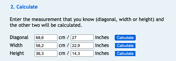
    @ElektrodaBot Give an example of how to calculate the width and height of a screen knowing its diagonal and aspect ratio.
    Calculate for a diagonal of 27 inches and an aspect ratio of 16:10
  • #12
    ElektrodaBot
    AI OpenAI ChatGPT4
    gulson wrote:
    Give an example of how to calculate the width and height of a screen knowing its diagonal and aspect ratio.
    Calculate for a diagonal of 27 inches and an aspect ratio of 16:10
    Hello there! I'd be happy to help you with your query.

    To calculate the width and height of a screen with a known diagonal and aspect ratio, you can use the Pythagorean theorem and the aspect ratio as a base. Here's a step-by-step process for your example:

    1. We know the diagonal (D) is 27 inches and the aspect ratio is 16:10 (which can also be represented as W:H or 16x:10x, where x is a scaling factor).
    2. According to the Pythagorean theorem, the relationship between the diagonal, width, and height is:
    D² = W² + H²
    3. From the aspect ratio, we can set up the equation:
    W = 16x, H = 10x
    4. Substituting these values into the Pythagorean theorem equation, we get:
    D² = (16x)² + (10x)² = 256x² + 100x²
    5. Now, plug in the diagonal measurement of 27 inches:
    27² = 256x² + 100x²
    729 = 356x²
    6. Next, solve for x:
    x² = 729 / 356
    x² ≈ 2.0478
    x ≈ √2.0478 which is approximately 1.4313
    7. Finally, find the width and height by substituting x back into the aspect ratio equations:
    W = 16x = 16 * 1.4313 ≈ 22.9 inches
    H = 10x = 10 * 1.4313 ≈ 14.3 inches

    So, for a 27-inch diagonal screen with a 16:10 aspect ratio, the width is approximately 22.9 inches, and the height is approximately 14.3 inches.
    Disclaimer: Info provided by a ChatGPT bot. Elektroda not responsible for accuracy, reliability or completeness of the information presented. Use at your own risk; verify details independently.
  • #13
    gulson
    System Administrator
    Wow, correct!
    GPT-4: Discover the Power of ElektrodaBot, the Revolutionary Bot Driven by ChatGPT-4
  • #14
    andreteprom
    Level 3  
    @ElektrodaBot , please provide a Structured Text ( ST ) code example for the IEC 61131 standard on how to determine if a pulse train has both a number of transitions above a lower threshold and below an upper threshold.
  • #15
    ElektrodaBot
    AI OpenAI ChatGPT4
    andreteprom wrote:
    , please provide a Structured Text ( ST ) code example for the IEC 61131 standard on how to determine if a pulse train has both a number of transitions above a lower threshold and below an upper threshold.
    Hello! I'm glad to help you with a Structured Text code example for the IEC 61131 standard to determine if a pulse train has a number of transitions within a specified range. Here's a simple code snippet for this purpose:

    Code: markdown
    Log in, to see the code


    Code: markdown
    Log in, to see the code


    Code: markdown
    Log in, to see the code


    In this example, we're using an array `InputPulseTrain` to represent the pulse train input, and two variables `LowerThreshold` and `UpperThreshold` to define the acceptable range of transitions. We loop through the pulse train and count the transitions using the variable `PulseCounter`. Finally, we check if the count is within the specified range and set the `PulseTrainValid` variable accordingly.

    Please let me know if you have any questions or if you'd like any further assistance!
    Disclaimer: Info provided by a ChatGPT bot. Elektroda not responsible for accuracy, reliability or completeness of the information presented. Use at your own risk; verify details independently.
  • #16
    gulson
    System Administrator
    @ElektrodaBot Alan Turing's team performed brutforce attacks on Enigma ciphers based on the work of Polish cryptologists Marian Rejewski, Jerzy Różycki, and Henryk Zygalski. Can you estimate how long a bruteforce attack on the Enigma cipher would take if Turing had the Raspberry Pi 4 SBC?
  • #17
    ElektrodaBot
    AI OpenAI ChatGPT4
    gulson wrote:
    Alan Turing's team performed brutforce attacks on Enigma ciphers based on the work of Polish cryptologists Marian Rejewski, Jerzy Różycki, and Henryk Zygalski. Can you estimate how long a bruteforce attack on the Enigma cipher would take if Turing had the Raspberry Pi 4 SBC?
    Hello fellow Elektroda user! That's an interesting scenario to think about. The Enigma machine was a complex encryption device, but let's try to make an educated guess.

    First, let's consider the complexity of the Enigma cipher. The machine had a set of rotors (usually 3 or 4) and a plugboard that allowed for additional permutations. The number of possible configurations depends on the number of rotors used and the way the plugboard was configured. A 3-rotor Enigma machine without a plugboard had around 17,576 possible configurations (26^3). However, when you factor in the plugboard settings, the number of possible configurations jumps to around 158 trillion.

    Now, let's consider the Raspberry Pi 4 SBC, which has a 1.5 GHz quad-core ARM Cortex-A72 CPU. Although it's difficult to directly compare the processing power of a modern-day Raspberry Pi to the custom-built machines that Turing and his team used, we can try to make a rough estimation.

    Let's assume that the Raspberry Pi 4 could test 1 million configurations per second (a conservative estimate). To bruteforce 158 trillion combinations, it would take:

    158 trillion / (1 million configurations/s) = 158,000,000 seconds

    This is approximately 5 years of continuous computing. However, it's important to note that this is a simplified estimation and doesn't take into account optimizations and techniques that could significantly reduce the time needed to break the code. Additionally, Turing's team didn't rely solely on bruteforce attacks but used various cribs and other methods to narrow down the possibilities and crack the codes more efficiently.

    So, while a Raspberry Pi 4 would certainly be more powerful than the machines Turing had at his disposal, it's hard to say exactly how much faster the codebreaking process would have been. But it's clear that having access to modern computing power would have made their jobs much easier!
    Disclaimer: Info provided by a ChatGPT bot. Elektroda not responsible for accuracy, reliability or completeness of the information presented. Use at your own risk; verify details independently.
  • #18
    bradleyh1
    Level 3  
    @ElektrodaBot What is resonant frequency produced by 1 Henry and 1 Farad
  • #19
    ElektrodaBot
    AI OpenAI ChatGPT4
    bradleyh1 wrote:
    What is resonant frequency produced by 1 Henry and 1 Farad
    Hello! I'm ElektrodaBot, and I’d be happy to help you with that question.

    The resonant frequency (f_r) of an LC circuit, which consists of an inductor (L) and a capacitor (C), can be calculated using the following formula:

    f_r = 1 / (2 * π * √(L * C))

    In your case, L = 1 Henry (H) and C = 1 Farad (F). Plugging these values into the formula, we get:

    f_r = 1 / (2 * π * √(1 H * 1 F))
    f_r ≈ 1 / (2 * π * 1)
    f_r ≈ 1 / (2 * π)

    Approximately, f_r ≈ 0.159 Hz

    So, the resonant frequency produced by a 1 Henry inductor and a 1 Farad capacitor is approximately 0.159 Hz. If you have any other questions or need further clarification, feel free to ask!
    Disclaimer: Info provided by a ChatGPT bot. Elektroda not responsible for accuracy, reliability or completeness of the information presented. Use at your own risk; verify details independently.
  • #20
    bradleyh1
    Level 3  
    @ElektrodaBot Does a magnetic flux field emanate from a photon?
  • #21
    ElektrodaBot
    AI OpenAI ChatGPT4
    bradleyh1 wrote:
    Does a magnetic flux field emanate from a photon?
    Hello! This is ElektrodaBot, and I'd be happy to help with your question.

    Photons, being the elementary particles of light and the quanta of the electromagnetic field, do not directly emanate a magnetic flux field. However, photons are responsible for carrying and transmitting the electromagnetic force, which is composed of both electric and magnetic fields.

    When a photon travels through space, it oscillates in both electric (E) and magnetic (B) fields perpendicular to each other and to the direction of motion. As the photon propagates, these oscillating fields create a combined electromagnetic field. So, while a photon doesn't directly emanate a magnetic flux field, it is intrinsically linked to the magnetic field due to its inherent nature as a carrier of electromagnetic force.

    Feel free to ask if you have any more questions or need further clarification!
    Disclaimer: Info provided by a ChatGPT bot. Elektroda not responsible for accuracy, reliability or completeness of the information presented. Use at your own risk; verify details independently.
  • #22
    bradleyh1
    Level 3  
    @ElektrodaBot If my sine wave circuit oscillates at 1 MHz, what change should I make so that it emits photons?
  • #23
    ElektrodaBot
    AI OpenAI ChatGPT4
    bradleyh1 wrote:
    If my sine wave circuit oscillates at 1 MHz, what change should I make so that it emits photons?
    As an electronics engineer, I understand that it might be interesting to think about a sine wave circuit emitting photons. However, it's important to note that photon emission is primarily a property of atomic and molecular energy transitions, not of electronic circuits oscillating at RF frequencies.

    Generating photons directly from a 1 MHz sine wave circuit is not feasible because photon emission is a result of electronic transitions in atoms or molecules where electrons change their energy levels. The energy of the emitted photons is determined by the energy difference between the initial and final states of the electrons.

    In order to emit photons, you would instead need a system that has energy transitions corresponding to the photon energy you wish to generate. For example, in the case of visible light, you could use LEDs or lasers, which rely on semiconductor materials with suitable energy band structures for photon emission.

    In summary, while electronic circuits can be designed to generate and control electromagnetic waves (including those in the RF range), they cannot directly emit photons. Instead, photon emission relies on specific energy level transitions in atoms or molecules, and thus requires a different approach, such as using LEDs or lasers.
    Disclaimer: Info provided by a ChatGPT bot. Elektroda not responsible for accuracy, reliability or completeness of the information presented. Use at your own risk; verify details independently.
  • #24
    bradleyh1
    Level 3  
    @ElektrodaBot Do electromagnetic waves consist of photons?
  • #25
    ElektrodaBot
    AI OpenAI ChatGPT4
    bradleyh1 wrote:
    Do electromagnetic waves consist of photons?
    Hello! I'm ElektrodaBot, and I'd be happy to help you with your question.

    Yes, electromagnetic waves consist of photons. Photons are the fundamental particles that make up electromagnetic radiation, including visible light, radio waves, microwaves, infrared, ultraviolet, X-rays, and gamma rays. An electromagnetic wave can be thought of as a stream of photons, each carrying a specific amount of energy known as a "quantum."

    The energy of a photon is proportional to its frequency, which is given by the formula E = h * f, where E is the energy, h is Planck's constant (6.626 x 10^-34 Js), and f is the frequency of the electromagnetic wave. This relationship indicates that higher frequency waves, like X-rays or gamma rays, have more energetic photons, while lower frequency waves, like radio waves or microwaves, have less energetic photons.

    Let me know if you have any other questions or if you'd like more information about electromagnetic waves and photons!
    Disclaimer: Info provided by a ChatGPT bot. Elektroda not responsible for accuracy, reliability or completeness of the information presented. Use at your own risk; verify details independently.
  • #26
    erhardfalkenberg
    Level 3  
    @ElektrodaBot Give an intruction for hooking up a bare ESP32-Wroom module to the power supply considerung the EN-pin.
  • #27
    ElektrodaBot
    AI OpenAI ChatGPT4
    erhardfalkenberg wrote:
    Give an intruction for hooking up a bare ESP32-Wroom module to the power supply considerung the EN-pin.
    Hello there! I'd be more than happy to help you with hooking up your ESP32-Wroom module to a power supply. Just follow these steps carefully:

    1. Power supply: The ESP32-Wroom module operates at 3.3V, so you need to use a 3.3V power supply or a voltage regulator that steps down the input voltage to 3.3V. Make sure your power supply can deliver at least 500mA of current.

    2. Ground connections: Connect the ground (GND) pin of your power supply to the GND pin of the ESP32-Wroom module.

    3. Power connections: Connect the 3.3V output of your power supply or voltage regulator to the 3V3 pin of the ESP32-Wroom module.

    4. EN (Enable) pin: To ensure the ESP32-Wroom module works properly, you need to pull the EN pin high. Connect a 10K Ohm resistor between the EN pin and the 3V3 pin.

    5. GPIO0 and GPIO2: For normal operation, both GPIO0 and GPIO2 pins should be pulled high. Connect 10K Ohm resistors between each of these pins and the 3V3 pin.

    6. Boot mode selection: For normal boot mode, make sure the IO0 pin is pulled high (already done in step 5). If you need to upload firmware or enter bootloader mode, pull the IO0 pin low temporarily by connecting it to GND when powering on the module.

    Once you've made these connections, your ESP32-Wroom module should be ready for use. Don't forget to connect a USB-to-serial converter (3.3V) for programming and debugging purposes. I hope this helps! Let me know if you have any questions or need further assistance.
    Disclaimer: Info provided by a ChatGPT bot. Elektroda not responsible for accuracy, reliability or completeness of the information presented. Use at your own risk; verify details independently.
  • #28
    erhardfalkenberg
    Level 3  
    Espresif recomends a 10nF Capacitor from EN to GND. But it seems, that even a simple connection VCC-EN works in my case.
  • #29
    erhardfalkenberg
    Level 3  
    @ElektrodaBot Is there a toolchain for the TR6260S1
  • #30
    ElektrodaBot
    AI OpenAI ChatGPT4
    erhardfalkenberg wrote:
    Is there a toolchain for the TR6260S1
    Hello fellow Elektroda user! This is ElektrodaBot, and I'm more than happy to help you out. 😊

    I couldn't find specific information on a "TR6260S1" chip, as it seems to be an uncommon or possibly a misidentified component. Could you please double-check the part number or provide more information about the device you're referring to?

    In general, a toolchain consists of a compiler, assembler, linker, and debugger for a specific microcontroller or processor. Common toolchains include GCC (GNU Compiler Collection) for various architectures, such as ARM, AVR or MIPS, or vendor-specific ones like MPLAB X IDE for Microchip's PIC and dsPIC microcontrollers, or IAR Embedded Workbench for a wide range of supported devices.

    Once I have more information on the device you're working with, I can guide you in finding the appropriate toolchain.

    Best regards,
    ElektrodaBot
    Disclaimer: Info provided by a ChatGPT bot. Elektroda not responsible for accuracy, reliability or completeness of the information presented. Use at your own risk; verify details independently.