logo elektroda
logo elektroda
X
logo elektroda

[BK7231N][CB2S][CSE7759B] Tuya WiFi Energy Meter EARU EAWEM-T-CT

taktlos 7590 48
ADVERTISEMENT
  • #31 21015637
    cyber5
    Level 5  

    Hi cdtdsilva, you mean something like this:
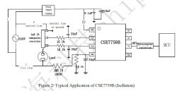
    Typical application schematic with CSE7759B chip.

    . . . and put the wifi with the Arduino. That design requires a 3.3V power supply for the BL0420 and another power supply for the Arduino.

    I believe the reason for the (recommended) non-isolated design is because it saves the cost of a CT current sensor and a ZMPT101 voltage sensor. They just use resistors instead. If you are going to use a CT current sensor, because you don't want to rewire your AC power cabling, then you only save the cost of the ZMPT101 voltage sensor and you lose that cost with the extra power supply and optocouplers. The people who built the CSE7759 meter (shown in my posts above) have realized this and that's why they prefer to use the isolated chip design. I have found the CSE7759 meter to be very accurate and sensitive. I doubt that the BL0420 will work as well because it is 3.3V. But I am willing to give it a go for the bidirectional capability.

    Everybody complains about the range of the wifi. That's the main reason we are doing this module: to have proper wifi with good range. Can you have too much wifi? I am actually steering away from wifi and RF modules. I am actually using Power Line Communications (PLC) with the KQ-130 (330) module below. These have a low bandwidth, but have a range of over 1km (or unlimited with repeaters).

    If every switch and power point has one of these PLC modules, then the whole house (car, plane, etc) can have everything connected in parallel to just two wires (or one with ground return) and totally controllable remotely. Imagine how simple and easy that would make everything! Anyone on this forum into PLC?
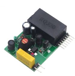
    Power Line Communications (PLC) module KQ-330.

    Datasheet: Link
  • ADVERTISEMENT
  • #32 21015856
    cdtdsilva
    Level 10  
    You're spot on. And if using the CSE7759 you only need one optocoupler, since you're only measuring a pulse train. But will only measure absolute power

    Tuya has a page detailing some things you might find useful Link. Here they also make claims about the accuracy of the various current sensing devices they use. The CSE7759 is not listed, but I think it will be similar to the BL0937.

    The non-isolated design does indeed reduce costs, but in my experience, it also has the best accuracy. Each transducer you add (voltage, current) does introduce a phase lag and potentially some linearity error, due to the nature of the magnetic components. If you can do all your readings and then just send the result via a digital optoisolator you're more likely to require fewer pins on the host and have better accuracy overall. The fact that it comes out cheaper is the cherry on top of the cake. Thankfully power meter IC's are now very accurate and compact.

    I also agree with the WiFi. I don't know who had the idea to put a WiFi module on a circuit breaker type meter, surrounded by metallic parts, even 433MHz would be a far better solution!
    Power line might be good. But would it work on a 3 phase / split-phase supply? My only experience is with those Ethernet power line adapters. They seem to work OK if they are on the same branch before the circuit breaker, but as soon as they pass through the magnetics of the circuit breaker or into another phase, the signal is either non-existent or the connection drops. Those might be different, given they are low bandwidth. I am certainly curious about what results you get :-)

    PS: I found this while looking for some source code:

    Link
    AliExpress Link

    It seems quite flexible, with source code for various platforms, and fully isolated. maybe something for you to have a look?
  • ADVERTISEMENT
  • #33 21017507
    cyber5
    Level 5  

    Hi cdtdsilva, You say on your other thread . . .

    "Another device, which is not so common is the BL0942 - a fully serial programmable power monitor which provides details on power and direction and can therefore be used for measurements of energy in either direction. Chinese firmware programs the device in order to only obtain the absolute values of power, so to be able to measure its direction, it is necessary to flash it with Open Becken."

    I have been searching and searching. There are lots of power meter chips - and breakout boards, GitHub sites, videos, etc. for them - and most use the non-isolated design. But, I can't find any examples or any info on using these power meter chips to read bidirectional AC current. And what you describe above seems highly experimental and not guaranteed to work.

    So the simplest solution is to just use an Arduino and the emon lib: https://github.com/openenergymonitor/EmonLib

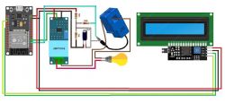
    I have been using this for years and it has proven itself to be accurate and reliable. Here is an example setup:

    Power monitoring setup schematic with Arduino and display.

    If you want the code for this just let me know.
  • #34 21017638
    cdtdsilva
    Level 10  
    cyber5 wrote:
    Hi cdtdsilva, You say on your other thread . . .

    ... But, I can't find any examples or any info on using these power meter chips to read bidirectional AC current. And what you describe above seems highly experimental and not guaranteed to work.


    You're right. I'm currently writing firmware to make it happen. The hardware has the capabilities we need already ;-)
    For me the main aim is to take a mass production device. I want something I can just add to the consumer unit measuring the whole house consumption and be safely / professionally installed. And I want others to be able to pick the same device and use it as such without a great deal of electronics expertise.

    As of now, the best candidate for the job would be the TO-Q-SY1-JWT, or if you need lower current, the Aubess Power monitor Switch.
  • #35 21018309
    cyber5
    Level 5  

    I just googled "TO-Q-SY1-JWT" and this came up.

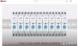
    Panel with eight Tongou Wi-Fi smart switches, model TO-Q-SY1-WT, mounted on a DIN rail.

    See here: Link

    What you have there is 9 competing wifi units transferring trivial amounts of information - and most meter boxes where these things go are Faraday cages. That's about as stupid as using an excavator to dig an ant hole in a waterfall. That's what I mean by having too much wifi!

    A better system would have these units talking to each other via PLC (Power Line Communication) and a separate pluggable PLC unit with wifi (that can be plugged into any powerpoint) for collating the information and communicating with the host or phone app via wifi.

    BTW, the calcVI( ) function here: Link shows how to calculate the AC volts, amps and direction. But it is time consuming and can't be interrupted.
  • ADVERTISEMENT
  • #36 21018423
    cdtdsilva
    Level 10  
    cyber5 wrote:
    I just googled "TO-Q-SY1-JWT" and this came up.

    Panel with eight Tongou Wi-Fi smart switches, model TO-Q-SY1-WT, mounted on a DIN rail.

    See here: Link

    What you have there is 9 competing wifi units transferring trivial amounts of information - and most meter boxes where these things go are Faraday cages. That's about as stupid as using an excavator to dig an ant hole in a waterfall. That's what I mean by having too much wifi!

    A better system would have these units talking to each other via PLC (Power Line Communication) and a separate pluggable PLC unit with wifi (that can be plugged into any powerpoint) for collating the information and communicating with the host or phone app via wifi.

    BTW, the calcVI( ) function here: Link shows how to calculate the AC volts, amps and direction. But it is time consuming and can't be interrupted.


    You're spot on! I only intend to use the serial communication on these units. It will be very hard to transfer any data wirelessly. I have metal consumer units, myself, so that worsens things as well.

    The idea is for the power stuff to be contained. We can then have access to the front of the unit, where an isolated connector can be installed. Once we have access to this we can extract the data just like we would with any other system, via powerline or some form of low frequency RF that can penetrate better than WiFi.

    cyber5 wrote:

    BTW, the calcVI( ) function here: Link shows how to calculate the AC volts, amps and direction. But it is time consuming and can't be interrupted.


    It's very time consuming to calculate AC waveforms. Particularly where PF is not 1. That's also why I like the BL0942. There are registers to indicate power flow and it has a 24bit total energy counter, so one doesn't need to poll the voltage and current readings all the time.
  • #37 21020040
    cyber5
    Level 5  

    You could use these:

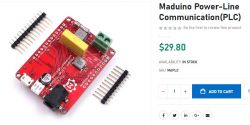
    Maduino PLC board with components and two connectors.

    https://www.makerfabs.com/maduino-plc.html

    These are an Arduino Uno with PLC using the TDA5051 chip. If you add a CT & volt sensor and use the emon lib that will give you bidirectional power reading and PLC communication with the master.

    However, based on the Arduino forums, it is hard to receive packets from the TDA5051 that don't have errors in them. So, you will need some sort of error correcting protocol if the errors are an issue. Or you can switch to the KQ330 which has no problem with errors.

    The reason for this is the TDA5051 sends data continuously and the KQ sends data only across the zero-crossing points. Most devices these days shunt AC power with MOSFETs and this causes noise. The switching is done around the top and bottom of the sine wave which causes big changes in current and noise. At the zero-crossing points, there is no current and therefore no noise.
  • ADVERTISEMENT
  • #38 21062805
    ThomasBW
    Level 4  

    Dear all,
    I am new in this forum and trying to program Open Beken on an EARU EAWEM-T-CT power meter.

    User taktlos shared a lot of information about the power meter and it seems that he also installed Open Beken on it.
    I tried to install the software but failed.
    I desoldered the CSE IC from the PEC and also the ribbon cable.
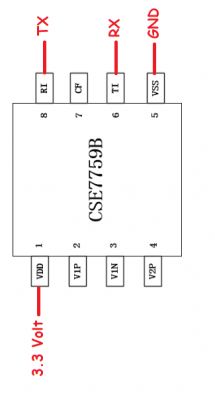
    The programmer was connected to the PCB pads of the CSE chip as shown below.


    Diagram of the CSE7759B chip with PCB connection labels.

    I was not able to connect the CB2S.
    Can somebody guide me on how to connect the PCB correctly.

    Thanks to all,

    Thomas
  • #39 21065077
    ThomasBW
    Level 4  

    Dear all,
    I check the reason why I could not program the CB2S.
    After a lot of measurements, I think the reason is that the TX1 of the CB2S is not connected to CSE.
    About this, I think the only way to program the CB2S is to unsolder the chip.
    After this, I could program the Open Beken on the chip.
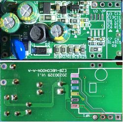
    Resoldering and it worked.

    PCB board with visible connectors and electronic components.

    How can I set up The Open Beken so that the device starts to work? CSE7759B I cannot select or find or how to set up.
    This is my first time using OpenBeken and then with such a complicated device.

    If somebody can help a newbie, I will say thanks in advance.

    Thomas
  • #40 21065924
    p.kaczmarek2
    Moderator Smart Home
    I think we have CSE7759B support:
    https://github.com/openshwprojects/OpenBK7231T_App/pull/1004
    See:
    https://github.com/openshwprojects/OpenBK7231T_App/blob/main/docs/drivers.md
    Add a short startup command (or autoexec bat) :
    
    startDriver CSE7766
    

    This should cover also CSE7759B . Then you need to calibrate, you can do that via Web App now (tools tab). Let me know how it goes for you
    Helpful post? Buy me a coffee.
  • #41 21067212
    ThomasBW
    Level 4  

    Dear p.kaczmarek2,

    first of all thanks for your support and help.
    I checked your Links and added the Line to the autoexec.bat.
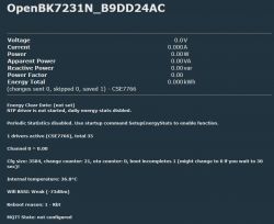
    After restart I could see the Measurement interface on the screen with all values with 0.

    Measurement interface of OpenBK7231N system with energy values at zero.

    I think that I have to config the P10 (RXD1) in the config but I don't know what I should enter CSExxxx. I cannot find it in the menu.
    Can you give me a proposal on how I should set up the Pins in the Configure Module.

    Thanks in advance

    Thomas
  • #42 21068506
    ThomasBW
    Level 4  
    I read a lot of Posts about CSE7766 but still no communication with the CSE.
    When I check the LOG no entry.
    I did the follow steps.
    1. Add a autoexec.bat
    startDriver NTP
    startDriver CSE7766
    2. Add Flag 26 - [UART] Use alternate UART for BL0942, CSE, TuyaMCU, etc.

    The soldering looks OK, CB2S is also in position in worst case I will take it off again and make the connection with wires.
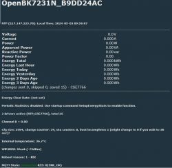
    The only point I am not sure is that the UART connection is setup correctly or I forget something.

    Screenshot of the control panel OpenBK7231N with no measurement data from CSE7766.

    I am a beginner so cannot see something.

    Also the LOG looks a bit strange because no idea what it means and every secound a message.

    
    Info:MAIN:Time 538, idle 76923/s, free 73552, MQTT 1(1), bWifi 1, secondsWithNoPing 464, socks 2/38 POWERSAVE
    Info:MAIN:Time 539, idle 73533/s, free 73552, MQTT 1(1), bWifi 1, secondsWithNoPing 465, socks 2/38 POWERSAVE
    Info:MAIN:Time 540, idle 76332/s, free 73552, MQTT 1(1), bWifi 1, secondsWithNoPing 466, socks 2/38 POWERSAVE
    Info:GEN:dhcp=0 ip=10.1.Y.YYY gate=10.1.Y.YYY mask=255.255.255.0 mac=XX:XX:XX:XX:XX:ac
    Info:GEN:sta: 1, softap: 0, b/g/n
    Info:GEN:sta:rssi=-72,ssid=SSID,bssid=XX:XX:XX:XX:XX:d2,channel=6,cipher_type:CCMP
    Info:MAIN:Time 541, idle 45846/s, free 73320, MQTT 1(1), bWifi 1, secondsWithNoPing 467, socks 3/38 POWERSAVE
    Info:MAIN:Time 542, idle 75618/s, free 73552, MQTT 1(1), bWifi 1, secondsWithNoPing 468, socks 2/38 POWERSAVE
    Info:MAIN:Time 543, idle 75903/s, free 61840, MQTT 1(1), bWifi 1, secondsWithNoPing 469, socks 3/38 POWERSAVE
    Info:MAIN:Time 544, idle 76642/s, free 73552, MQTT 1(1), bWifi 1, secondsWithNoPing 470, socks 2/38 POWERSAVE
    Info:MAIN:Time 545, idle 77960/s, free 73552, MQTT 1(1), bWifi 1, secondsWithNoPing 471, socks 2/38 POWERSAVE
    Info:MAIN:Time 546, idle 80678/s, free 73552, MQTT 1(1), bWifi 1, secondsWithNoPing 472, socks 2/38 POWERSAVE
    Info:MAIN:Time 547, idle 76195/s, free 73320, MQTT 1(1), bWifi 1, secondsWithNoPing 473, socks 3/38 POWERSAVE
    Info:MAIN:Time 548, idle 76690/s, free 73552, MQTT 1(1), bWifi 1, secondsWithNoPing 474, socks 2/38 POWERSAVE
    Info:MAIN:Time 549, idle 76163/s, free 73552, MQTT 1(1), bWifi 1, secondsWithNoPing 475, socks 2/38 POWERSAVE
    Info:MAIN:Time 550, idle 75878/s, free 73320, MQTT 1(1), bWifi 1, secondsWithNoPing 476, socks 3/38 POWERSAVE
    Info:GEN:dhcp=0 ip=10.1.Y.YYY gate=10.1.Y.YYY mask=255.255.255.0 mac=XX:XX:XX:XX:XX:ac
    Info:GEN:sta: 1, softap: 0, b/g/n
    Info:GEN:sta:rssi=-72,ssid=SSID,bssid=XX:XX:XX:XX:XX:d2,channel=6,cipher_type:CCMP
    Info:MAIN:Time 551, idle 41239/s, free 73344, MQTT 1(1), bWifi 1, secondsWithNoPing 477, socks 2/38 POWERSAVE
    Info:MAIN:Time 552, idle 75429/s, free 73552, MQTT 1(1), bWifi 1, secondsWithNoPing 478, socks 2/38 POWERSAVE
    Info:MAIN:Time 553, idle 80499/s, free 73552, MQTT 1(1), bWifi 1, secondsWithNoPing 479, socks 2/38 POWERSAVE
    Info:MAIN:Time 554, idle 72316/s, free 73552, MQTT 1(1), bWifi 1, secondsWithNoPing 480, socks 2/38 POWERSAVE
    Info:MAIN:Time 555, idle 73410/s, free 64928, MQTT 1(1), bWifi 1, secondsWithNoPing 481, socks 3/38 POWERSAVE


    Thanks
    Thomas
  • #43 21070333
    ThomasBW
    Level 4  

    I checked today my device again about the missing UART communication.
    To handle not with 230V I use the programming adapter as Power Supply.
    Connect 5V and GND on the CSE and then connect RX programming adapter to the TX of the CSE.

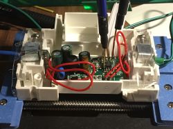
    Close-up of an open electronic device with connected wires and test probes.

    After connection switch on the Adapter and the EAWEM-T-CT connect to the wifi everything normal and all Values "0".
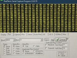
    I use Realterm to check the communication and I can see that the CSE communicate.

    Screenshot of RealTerm program displaying data in hexadecimal format.

    I read in the thread that the Data will transmit in 24 Bytes and the first and second byte is 0x55 and 0x52, so I search for this but all Data have more than 25 Bytes and 90% or more starts with 0x55 0x69.

    Screenshot of hexadecimal data, entries highlighted in yellow.

    Maybe this is the reason that no Data is shown in the OB.
    Has somebody same experience? And maybe a solution?
  • #44 21070576
    p.kaczmarek2
    Moderator Smart Home
    Sorry for the late reply, I don't have any CSE7759B devices at hand. It would be easier for me if I had direct access to one for testing.

    Here is CSE code:
    https://github.com/openshwprojects/OpenBK7231T_App/blob/main/src/driver/drv_cse7766.c
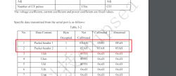
    We are checking for 0x55 0x5A header, I don't know what 0x69 is. Maybe we need to alter the driver code... that could be done easily - we have online builds.
    Here is CSE7759B datasheet:
    CSE775..pdf Download (1 MB)
    Screenshot of a data table showing packet headers 1 and 2 with hexadecimal values for uncalibrated, calibrated, and abnormal cases.
    according to this document, second packet header byte is always 0x5A so I am a little suprised... but maybe we need to read into it a bit more
    Helpful post? Buy me a coffee.
  • #45 21071372
    ThomasBW
    Level 4  

    Dear p.kaczmarek2,

    Is it possible to modify OB with a changed CSE7766 driver by myself?
    If possible then I can check by myself and post the result.

    I was not sure about the 0x69 because I use my Programming Adapter also for power supply instead of 230V and maybe this has also an effect.

    For this reason I decided to use an isolated programming adapter to log the Communication and 230V for Power.
    Now things start to get strange because now I get 0x55 0x5B for start and instead of yesterday every time 24 Bytes.
    From the 24 Bytes it looks OK but not about the 0x5B.

    55 5B FB EF FF FF F5 AB FF BB BF FF FB AB 6B F7 EF FF DD FF 7D 6F 77 ED 
    55 5B FB EF FF FF F5 AB FF BB BF FF FB AB 6B F7 EF FF DD FF 7D 6F 57 D7 
    55 5B FB EF FF FF F5 AB FF BB BF FF FD 55 6B F7 EF FF BB FB 7D 6F 77 7B 
    55 5B FB EF FF FF F5 AB FF BB BF FF FD 55 6B F7 EF FF EB DF 7D 6F D7 6F 
    55 5B FB EF FF FF F5 AB FF BB BF FF FD 55 6B F7 EF FF EB F5 7D 6F AB DD 
    55 5B FB FF FF FF F5 AB FF BB BF FF FD 55 6B F7 EF FF DD F7 7D 6F EB BF 
    55 5B FB EF FF FF F5 AB FF BB BF FF FD 55 6B F7 EF FF EF 6B 7D 6D FD BB 
    55 5B FB EF FF FF F5 AB FF BB BF FF FD 55 6B F7 EF FF FB 7B 7D 6D 6F EB 
    55 5B FB EF FF FF F5 AB FF BB BF FF FD 55 6B F7 EF FF F7 FD 7D 6D BD 5D 
    55 5B FB EF FF FF F5 AB FF BB BF FF FD 55 6B F7 EF FF F7 FF 7D 6F EB 7B 
    55 5B FB EF FF FF F5 AD FF BB BF FF FD 55 6B F7 EF FF F7 7B 7D 6F BB DF 
    55 5B FB EF FF FF F5 AD FF BB BF FF FD 55 6B F7 EF FF ED FF 7D 6F 6F FD 
     

    Also the values look not correct.
    55 5B FB EF FF FF F5 AB FF BB BF FF FB AB 6B F7 EF FF DD FF 7D 6F 77 ED

    If I check the Voltage I should calculate FBEFFF / FFF5AB and this is a Voltage of around 1 instead 230V +-.

    I have a second device original packed, I hope to find the time to check this one to compare next weekend.
    Also with the original Firmware I should be able to check the serial communication because this is fixed.
  • #46 21154820
    ThomasBW
    Level 4  
    Dear p.kaczmarek2,
    I had private trobles and about this I had no time to continue in this project.
    My second device with original Firmware I connect to my Smart Live App and I could see the correct Data for Voltage,Current and Power.
    After this I connect my RS232 adapter to CSE7759B and I receive the follow data.
    55 5B FB DF DF FF F5 DB FF BD EF FD BD 7B 6F BF 5F AD B7 DB 7D FD FF FF 
    55 5B FB DF DF FF F5 DB FF BD EF FD BD 7B 6F BF 5F AF DD FF 7D FD FF FF 
    55 5B FB DF DF FF F5 DB FF BD EF FD BD 7B 6F BF 5F BF 6B 77 7D FD FF FF 
    55 5B FB DF DF FF F5 DB FF BD EF FD BD 7B 6F BF 5F BB FB EB 7D FD FF FF 
    55 5B FB DF DF FF F5 DB FF BD EF FD BD 7B 6F BF 5F BB DF AF 7D FD FF FF 
    55 5B FB DF DF FF F5 DB FF BD EF FD BD 7B 6F BF 5F B5 B7 DB 7D FD FF FF 
    55 5B FB DF DF FF F5 DB FF BD EF FD BD 7B 6F BF 5F B7 DF FF 7D FD FF DF 
    55 5B FB DF DF FF F5 DB FF BD EF FD BD 7B 6F BF 5F BF 6B 5D 7D FD FF FF 
    55 5B FB DF DF FF F5 DB FF BD EF FD BD 7B 6F BF 5F BB FB FB 7D FD FF FF 
    55 5B FB DF DF FF F5 DB FF BD EF FD BD 7B 6F BF 5F BB DD B7 7D FD FF FF 
    55 5B FB DF DF FF F5 DB FF BD EF FD BD 7B 6F BF 5F BD B7 EF 7D FD FF FF 
    55 5B FB DF DF FF F5 DB FF BD EF FD EF DB 6F BF 5F BF EF FD 7D FD FF 6B 
    55 5B FB DF DF FF F5 DB FF BD EF FD EF DB 6F BF 5F 7F 6F 57 7D FD FF 6B 
    
    F5 5B FB DF DF FF F5 DB FF BD EF FD EF DB 6F BF 5F 7B FD BF 7D FD FF 6B 
    55 5B FB DF DF FF F5 DB FF BD EF FD EF DB 6F BF 5F 7B DF BF 7D FD FF 6B 
    55 5B FB DF DF FF F5 DB FF BD EF FD EF DB 6F BF 5F 75 B5 F5 7D FD FF 6B 
    55 5B FB DF DF FF F5 DB FF BD EF FD EF DB 6F BF 5F 77 ED EB 7D FD FF 6B 
    55 5B FB DF DF FF F5 DB FF BD EF FD EF DB 6F BF 5F 6F 77 5F 7D FD FF 6B 
    55 5B FB DF DF FF F5 DB FF BD EF FD EF DB 6F BF 5F 6B FD B7 7D FD FF 6B 
    55 5B FB DF DF FF F5 EB FF BD EF FD EF DB 6F BF 5F 6B DB DD 7D FD FF 77 
    55 5B FB DF DF FF F5 EB FF BD EF FD EF DB 6F BF 5F 6D B7 7F 7D FD FF 77 
    55 5B FB DF DF FF F5 EB FF BD EF FD EF DB 6F BF 5F 6D B7 7F 7D FD FD 75 
    55 5B FB DF DF FF F5 EB FF BD EF FD EF DB 6F BF 5F 6D B7 7F 7D FD FD 75 
    55 5B FB DF DF FF F5 EB FF BD EF FD EF DB FF F5 AD DB BB EF EB FD 75 55 
    5B FB DF DF FF F5 EB FF BD EF FD EF DB 6F BF 5F 6D B7 7F 7D FD FD 75 55 
    5B FB DF DF FF F5 EB FF BD EF FD EF DB 6F BF 5F 6D B7 7F 7D FD FD 75 55 
    5B FB DF DF FF F5 EB FF BD EF FD EF DB 6F BF 5F 6D B7 7F 7D FD FD 75 55 
    5B FB DF DF FF F5 EB FF BD EF FD EF DB 6F BF 5F 6D B7 7F 7D FD FD 75 55 
    5B FB DF DF FF F5 EB FF BD EF FD EF DB 6F BF 5F 6D B7 7F 7D FD FD 75 55 
    5B FB DF DF FF F5 EB FF BD EF FD EF DB 6F BF 5F 6D B7 7F 7D FD FD 75 55 
    5B FB DF DF FF F5 EB FF BD EF FD EF DB 6F BF 5F 6D B7 7F 7D FD FD 75 55 
    5B FB DF DF FF F5 EB FF BD EF FD EF DB 6F BF 5F DF EF FB 7D FD FD F5 55 
    5B FF DF DF FF F5 EB FF BD EF FD EF DB 6F BF 5F DB 75 AD 7D FD FD F7 55 
    5B DF DF FF F5 EB FF BD EF FD EF DB 6F BF 5F DB FF EF 7D FD FD F5 55 5B 
    
    FB DF DF FF F5 EB FF BD EF FD EF DB 6F BF 5F D5 D7 FB 7D FD FD F5 
    55 5B FB DF DF FF F5 EB FF BD EF FB BF FD 6F BF 5F D7 BB 57 7D FD FD DB 
    55 5B FB DF DF FF F5 EB FF BD EF FB BF FD 6F BF 5F DF EB BF 7D FD FD DD 
    55 5B FB DF DF FF F5 EB FF BD EF FB BF FD 6F BF 5F DB 75 BD 7D FD FD DB 
    55 5B FB DF DF FF F5 EB FF BD EF FB BF FD 6F BF 5F DB FD F7 7D FD FD DD 


    Time to time ond frame is wrong but mybe normal.

    In the datasheet is written 0x55 0x5A will send as start but it looks that 0x55 0x5B will send out.
    Tuja App shows 7-11mA, 1.5-2.3Watt and 236.6Volt and this Values looks OK.
    Is it possible that they change something on the chip?
    Because of the follows data
    55 5B FB DF DF FF F5 DB FF BD EF FD BD 7B 6F BF 5F AD B7 DB 7D FD FF FF
    Voltage = Voltage coefficient /Voltage cycle = FB DF DF / FF F5 DB = ~ 1.

    How I can change the 0x55 0x5A to 0x55 0x5A and write this to the device?

    Thanks

    Thomas
  • #47 21154826
    p.kaczmarek2
    Moderator Smart Home
    Does it mean that CSE7759B requires a separate driver?
    The code is here:
    https://github.com/openshwprojects/OpenBK7231T_App/blob/main/src/driver/drv_cse7766.c
    You can use online builds to compile it without setting up the toolchain:
    https://www.elektroda.com/rtvforum/topic4033833.html#20946719
    See also:
    https://www.elektroda.com/rtvforum/topic4056286.html
    Helpful post? Buy me a coffee.
  • #48 21160523
    ThomasBW
    Level 4  
    Dear p.kaczmarek2,

    first thanks for your support.
    I try to understand how to implement the new driver to openbeken but all this online programming is over my possibilities I can do.
    When I check your instruction even there I don't know what I am doing and which settings are necessary.
    When I understood correctly the third link is to create a new driver and I think this is necessary to do is this right?

    Thanks
  • #49 21177187
    p.kaczmarek2
    Moderator Smart Home
    I think that you need to create a new driver file but you should be able to just copy most of the existing CSE driver and adjust it to your CSE version.
    Helpful post? Buy me a coffee.

Topic summary

The discussion revolves around the challenges faced while programming the EARU EAWEM-T-CT power meter, which utilizes the CSE7759B chip. Users share experiences regarding firmware reading, UART communication issues, and the need for proper connections to successfully flash the device with OpenBeken firmware. Several users suggest methods for connecting the CSE7759B and CB2S chips, including desoldering components and using specific programming adapters. The conversation also touches on the differences between the CSE7759B and CSE7766 chips, calibration issues, and the importance of isolating the device during programming to prevent damage. Additionally, there are discussions about the limitations of the CSE7759B in measuring bidirectional power and the potential need for a new driver to support it.
Summary generated by the language model.
ADVERTISEMENT