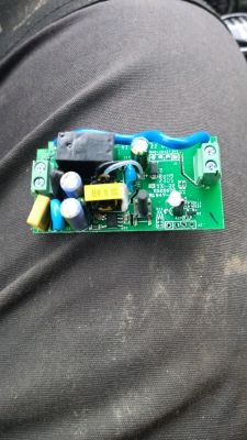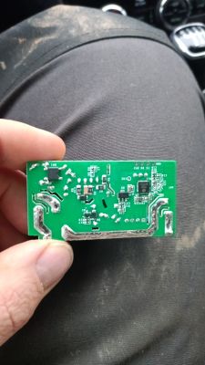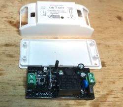
I invite you to a short presentation of the interior and the process of changing the firmware of a typical relay module, which is, in a sense, a Sonoff clone based on the WiFi+Bluetooth BK7231N microcontroller.
Purchase LXU402
A reader sent me several pieces of this relay so that I could upload it OpenBeken ,
As far as I know, he bought them in a Polish store, but this offer is no longer available. This is not a problem, as there are many other offers with LXU402:
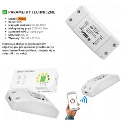
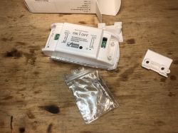
So let`s see what this product looks like in practice:
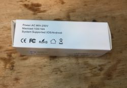
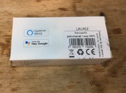
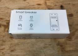
The dot next to WiFi+BT (and not next to WiFi itself) indicates that there is probably no ESP8266 inside, but there may be BK7231:
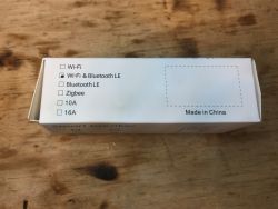
Set contents:
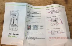
Instruction:
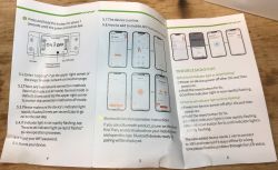
I will skip the test with the Tuya application, it has been tested many times.
LXU402 interior
We look inside:
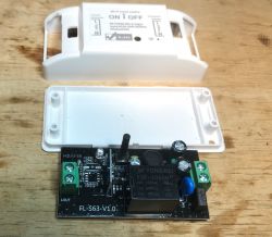
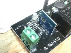
PCB name: FL-S63-V1.0
You can see here the place for the radio system, the SOIC8 element and the resonator. Y3F-105DM relay:
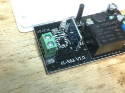
At least there is a fuse and a varistor at the input.
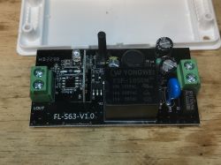
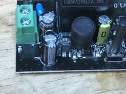
The entire BP2525 power supply (as usual! Non-isolated power supply, step down from the mains) and AMS1117-3.3V:
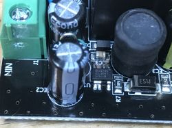
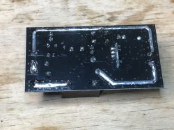
The current paths are bold (the relay cuts off only one wire):
ADVERTISEMENT
LXU402 firmware change
The easiest way is to desolder the module. All you need is flux and braid. This saves us from problems like "we have a button with a capacitor on TXD1 and it interferes with programming":
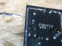
Desoldered:
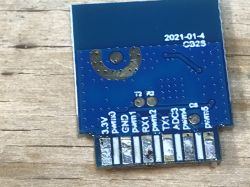
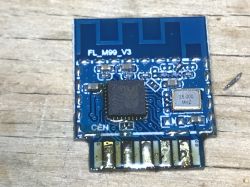
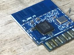
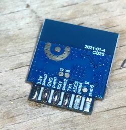
GPIOs are signed - we need 3.3V, GND, RX and TX.
We upload the batch according to:
https://github.com/openshwprojects/BK7231GUIFlashTool
First I whitened the pads:
Then I soldered the cables:
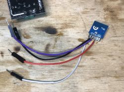
Here is my USB to UART and LDO 3.3V converter to power the WiFi module:
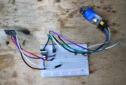
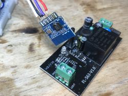
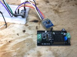
After performing the power off/on cycle, the flasher correctly programs this module and loads OpenBeken, having previously read the Tuya configuration:
Code: JSON
Interestingly, the FL_M99_V3 module is seen by Tuya as CB2S .
Verbal description:
Device configuration, as extracted from Tuya:
- Button (channel 1) on P23
- Pair/Toggle All Button on P7
- WiFi LED on P8
- Relay (channel 1) on P6
Device seems to be using CB2S module, which is using BK7231N.
And the Tuya section starts, as usual, at 2023424
OBK template generated by https://openbekeniot.github.io/webapp/templateImporter.html:
Code: JSON
After uploading OBK, you can, for example, pair with HA (Home Assistant Discovery) according to the guide on the Elektroda YT channel: https://www.youtube.com/@elektrodacom
Summary
Simple and fast flashing. Probably even simpler than in the case of ESP, because I soldered only 4 cables and not 5, and my BK7231 Easy Flasher detected the GPIO template itself, and in the case of Tasmota you would probably have to guess it manually, i.e. either test the pins one by one or trace the paths. This way, another device was freed from the cloud:
PS: Due to the poor quality and performance of power supplies in this type of products, I recommend turning them on in OBK PowerSave 1 to slightly save the capacitor at the converter output. This capacitor has happened several times I had to replace it ...
Cool? Ranking DIY Helpful post? Buy me a coffee.


