logo elektroda
logo elektroda
X
logo elektroda

[BK7231N CB2S] 2- and 3-channel WiFi flush-mount switches - description, photos, configuration OpenB

@GUTEK@ 3972 20
ADVERTISEMENT
Treść została przetłumaczona polish » english Zobacz oryginalną wersję tematu
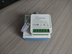
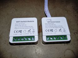
  • Two WiFi switch modules MINI-W1-2CH and MINI-W1-3CH lying on a surface.

    Hello.
    I haven`t found a configuration for these wall switches, so I`m posting my own. Bought on AliExpress: https://www.aliexpress.com/item/1005005773648155.html
    They are available in 1/2/3/4 channel versions. I have the 2 and 3 channel version.
    They have no manufacturer, neither on them nor on the box. Only the general model is MINI-W1, while specific versions are MINI-W1-2CH and MINI-W1-3CH.
    They are based on the BK7231N CB2S system and firmware 1.3.10. So at the moment they cannot be reprogrammed using CloudCutter.
    In the Smart Life application they are detected as PSW-2CH-CB2S and PSW-3CH-CB2S.

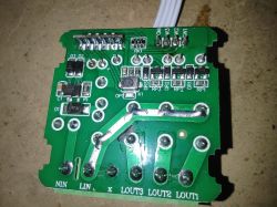
    The housing is assembled with 4 latches, which release quite easily when lifted. You can program without desoldering the module, but you need to connect an additional 3.3V power supply. Because it does not produce current from the UART converter.
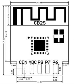
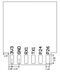
    Pinout:
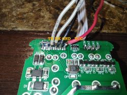
    Close-up of a printed circuit board with pin labels: TX, RX, GND, VCC and connected wires. Technical drawing of the CB2S module. Diagram of electrical module pins labeled 3V3, GND, RX1, TX1, P24, and P26.

    2 channel version (2 Gang):
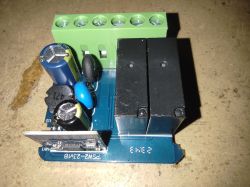
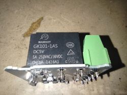
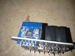
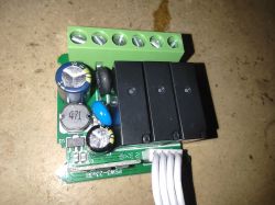
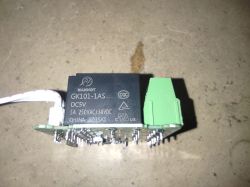
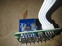
    MINI-W1-2CH WiFi switch module on packaging. PCB of a flush-mounted switch module WiFi switch module with two relays and electronic components. MANHOT GK101-1AS relay module on a work surface. WiFi switch module with BK7231N chip

    JSON configuration:
    {
    	"rl1_lv":"1",
    	"on_off_cnt":"10",
    	"onoff_rst_m":"1",
    	"onoff_clear_t":"10",
    	"rand_dpid":"42",
    	"net_trig":"4",
    	"onoff_n":"5",
    	"netled1_lv":"1",
    	"jv":"110.0.0",
    	"onoff_rst_type":"2",
    	"ffc_select":"2",
    	"total_bt_pin":"23",
    	"nety_led":"2",
    	"total_stat":"0",
    	"reset_t":"5",
    	"netled1_pin":"11",
    	"rl2_lv":"1",
    	"remote_add_dp":"49",
    	"remote_list_dp":"50",
    	"net_type":"0",
    	"inch_dp":"44",
    	"module":"CB2S",
    	"ch_cddpid1":"9",
    	"inch_en2":"0",
    	"inch_en1":"0",
    	"onoff1":"6",
    	"ble_pair_time":"30",
    	"onoff2":"7",
    	"clean_t":"5",
    	"init_conf":"38",
    	"rl2_pin":"24",
    	"zero_select":"0",
    	"onoff_type":"0",
    	"series_ctrl":"0",
    	"ch_cddpid2":"10",
    	"total_bt_lv":"0",
    	"cyc_dpid":"43",
    	"ch_num":"2",
    	"rl1_pin":"10",
    	"netn_led":"2",
    	"ch_dpid1":"1",
    	"ch_dpid2":"2",
    	"crc":"94",
    	"}>$Agw_di{abi":"0",
    	"id":"null",
    	"swv":"1.3.10",
    	"bv":"40.00",
    	"pv":"2.2",
    	"lpv":"3.4",
    	"pk":"keyjnuy4s3kre7m7",
    	"firmk":"keyjnuy4s3kre7m7",
    	"cadv":"1.0.5",
    	"cdv":"1.0.0",
    	"dev_swv":"1.3.10",
    	"s_id":"null",
    	"dtp":"0",
    	"sync":"0",
    	"attr_num":"1",
    	"mst_tp_0":"9",
    	"mst_ver_0":"1.3.10",
    	"mst_md5_0":"null",
    	"mst_tp_1":"0",
    	"mst_ver_1":"null",
    	"mst_md5_1":"null",
    	"mst_tp_2":"0",
    	"mst_ver_2":"null",
    	"mst_md5_2":"null",
    	"mst_tp_3":"0",
    	"mst_ver_3":"null",
    	"mst_md5_3":"null }Ainch_time_key 0KAgw_wsm{nc_tp",
    	"ssid":"null",
    	"passwd":"null",
    	"md":"0",
    	"random":"0",
    	"wfb64":"1",
    	"stat":"0",
    	"token":"null",
    	"region":"null",
    	"reg_key":"null",
    	"dns_prio":"0 }{uuid",
    	"psk_key":"FDItek6yQeqW9EdJPm5SYUUf6XuntIwPvPwnO",
    	"auth_key":"5X00RcxhgeHaxlRPn9levSBYGlfAfjM7",
    	"ap_ssid":"SmartLife",
    	"ap_passwd":"null",
    	"country_code":"null",
    	"bt_mac":"null",
    	"bt_hid":"null",
    	"prod_test":"false",
    	"fac_pin":"sqgfy9njgvghohai }{nc_tp"
    }

    Device configuration, as extracted from Tuya: 
    - Pair/Toggle All Button on P23
    - WiFi LED on P11
    - TglChannelToggle (channel 1) on P6
    - TglChannelToggle (channel 2) on P7
    - Relay (channel 2) on P24
    - Relay (channel 1) on P10
    Device seems to be using CB2S module, which is using BK7231N.
    And the Tuya section starts, as usual, at 2023424


    Configuration for WebApp:
    {
      "vendor": "Tuya",
      "bDetailed": "0",
      "name": "MINI-W1 2-Gang WiFi Switch Module",
      "model": "MINI-W1-2CH",
      "chip": "BK7231N",
      "board": "PSW2-23v1B",
      "flags": "1024",
      "keywords": [
        "TODO",
        "TODO",
        "TODO"
      ],
      "pins": {
        "6": "TglChanOnTgl;1",
        "7": "TglChanOnTgl;2",
        "10": "Rel;1",
        "11": "WifiLED_n;0",
        "23": "Btn_Tgl_All;0",
        "24": "Rel;2"
      },
      "command": "",
      "image": "https://obrazki.elektroda.pl/4786852700_1704633029.jpg",
      "wiki": "https://www.elektroda.pl/rtvforum/topic4026798.html"
    }


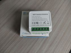
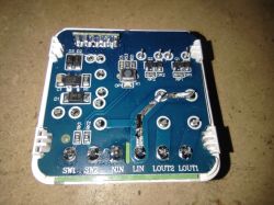
    3 channel version (3 Gang):
    MINI-W1-3CH WiFi switch module on a box with wiring Circuit board of the MINI-W1 WiFi switch module without casing. Photo of an electronic relay module from AliExpress Electronic relay module against a concrete surface. WiFi switch module with CB2S circuit and BK7231N chip on a circuit board.

    JSON configuration:
    {
    	"rl1_lv":"1",
    	"on_off_cnt":"10",
    	"onoff_rst_m":"1",
    	"rl3_pin":"26",
    	"rl3_lv":"1",
    	"onoff_clear_t":"10",
    	"rand_dpid":"42",
    	"net_trig":"4",
    	"onoff_n":"5",
    	"netled1_lv":"1",
    	"jv":"110.0.0",
    	"onoff_rst_type":"2",
    	"ffc_select":"2",
    	"total_bt_pin":"23",
    	"nety_led":"2",
    	"total_stat":"0",
    	"reset_t":"5",
    	"netled1_pin":"11",
    	"rl2_lv":"1",
    	"remote_add_dp":"49",
    	"remote_list_dp":"50",
    	"net_type":"0",
    	"inch_dp":"44",
    	"module":"CB2S",
    	"ch_cddpid1":"9",
    	"inch_en2":"0",
    	"inch_en3":"0",
    	"inch_en1":"0",
    	"onoff1":"6",
    	"ble_pair_time":"30",
    	"onoff2":"7",
    	"clean_t":"5",
    	"init_conf":"38",
    	"onoff3":"8",
    	"rl2_pin":"24",
    	"zero_select":"0",
    	"onoff_type":"0",
    	"series_ctrl":"0",
    	"ch_cddpid2":"10",
    	"ch_cddpid3":"11",
    	"total_bt_lv":"0",
    	"cyc_dpid":"43",
    	"ch_num":"3",
    	"rl1_pin":"10",
    	"ch_dpid3":"3",
    	"netn_led":"2",
    	"ch_dpid1":"1",
    	"ch_dpid2":"2",
    	"crc":"20",
    	"}Agw_di0Ainch_time_keyv":"40.00",
    	"pv":"2.2",
    	"lpv":"3.4",
    	"pk":"keyjnuy4s3kre7m7",
    	"firmk":"keyjnuy4s3kre7m7",
    	"cadv":"cdv",
    	"dev_swv":"1.3.10",
    	"s_id":"null",
    	"dtp":"0",
    	"sync":"0",
    	"attr_num":"1",
    	"mst_tp_0":"9",
    	"mst_ver_0":"1.3.10",
    	"mst_md5_0":"null",
    	"mst_tp_1":"0",
    	"mst_ver_1":"null",
    	"mst_md5_1":"null",
    	"mst_tp_2":"0",
    	"mst_ver_2":"null",
    	"mst_md5_2":"null",
    	"mst_tp_3":"0",
    	"mst_ver_3":"null",
    	"mst_md5_3":"null "
    }

    Device configuration, as extracted from Tuya: 
    - Relay (channel 3) on P26
    - Pair/Toggle All Button on P23
    - WiFi LED on P11
    - TglChannelToggle (channel 1) on P6
    - TglChannelToggle (channel 2) on P7
    - TglChannelToggle (channel 3) on P8
    - Relay (channel 2) on P24
    - Relay (channel 1) on P10
    Device seems to be using CB2S module, which is using BK7231N.
    And the Tuya section starts, as usual, at 2023424


    Configuration for WebApp:
    {
      "vendor": "Tuya",
      "bDetailed": "0",
      "name": "MINI-W1 3-Gang WiFi Switch Module",
      "model": "MINI-W1-2CH",
      "chip": "BK7231N",
      "board": "PSW3-23v3B",
      "flags": "1024",
      "keywords": [
        "TODO",
        "TODO",
        "TODO"
      ],
      "pins": {
        "6": "TglChanOnTgl;1",
        "7": "TglChanOnTgl;2",
        "8": "TglChanOnTgl;3",
        "10": "Rel;1",
        "11": "WifiLED_n;0",
        "23": "Btn_Tgl_All;0",
        "24": "Rel;2",
        "26": "Rel;3"
      },
      "command": "",
      "image": "https://obrazki.elektroda.pl/9026804300_1704633863.jpg",
      "wiki": "https://www.elektroda.pl/rtvforum/topic4026798.html"
    }


    The original firmware is downloaded in the attachments.

    Cool? Ranking DIY
    About Author
    @GUTEK@
    Level 31  
    Offline 
    @GUTEK@ wrote 1529 posts with rating 314, helped 161 times. Live in city Gliwice. Been with us since 2005 year.
  • ADVERTISEMENT
  • #2 20896541
    p.kaczmarek2
    Moderator Smart Home
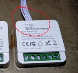
    I don`t think I`ve seen this version with the cables leading outside:
    WiFi switch module with external wires.
    I hope that the instructions contain appropriate warnings, because these devices have non-isolated converters, so there may be network potential on these cables led outside the housing... for this reason, it is worth being very careful, also when making any modifications, e.g. the firmware can be very easily connected to a free DHT11 pin and also receive humidity and temperature measurements in the HA.

    In addition, you must enable PowerSave 1 on these devices, otherwise there will be a repetition of:
    How to fix a smart device that is chirping, squeaking and making strange sounds?
    The data on these converters is limited, the manufacturer probably chose the cheapest ones available
    Helpful post? Buy me a coffee.
  • #3 20896674
    @GUTEK@
    Level 31  
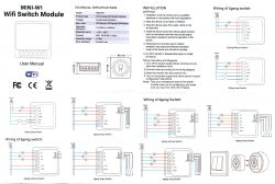
    Yes, the manual contains a warning, information that it should be connected by a qualified electrician, and connection diagrams for various versions.
    From what I measured, the cable described as COM is shorted to N-in and it is generally a ground on the board. Also, accidental reverse connection of the phase will also cause the phase to appear on the cable and the system will smoke when it is shorted.
    The remaining cables are connected to the inputs of the system and have 3.3V on them.

    Yes, you can connect some additional sensors, but is it worth buying a more expensive version with several weaker relays? You might as well buy a single one and run these 3 cables to the sensor, since you still have to open the housing and solder it in order to reprogram it.

    I am also attaching scans of the instructions.

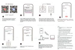
    User manual of MINI-W1 WiFi switch module with wiring diagrams. Scans of the user manual for the iOS and Android app to operate the Wi-Fi switch module.
  • #4 20934967
    @GUTEK@
    Level 31  
    I noticed a strange problem. I installed a 2-channel switch and after connecting the switch - bistable. When the switch is reset or started, the relay corresponding to the S2 input turns on. I have both inputs set as in the configuration above, i.e. TglChanOnTgl. Interestingly, if I do not set anything for P6 corresponding to S1, it does not happen. Also this does not occur when I change the configuration to Btn.
    For now I have added to autoexec.bat:
    SetChannel 1 0
    SetChannel 2 0
    However, despite this, the lamp flashes during startup.
  • #5 20935047
    p.kaczmarek2
    Moderator Smart Home
    The 2-channel version has one TglChanOnTgl on channel one and another TglChanOnTgl on channel two. Try swapping their channels.

    If only the S2 input is still to blame (those signed as S2, physically, not channel 2 from OBK), it is possible that it is a hardware issue.

    Alternatively, you could think about the role of TglChanOnTgl with configurable pull up or down resistors.
    Helpful post? Buy me a coffee.
  • ADVERTISEMENT
  • #6 20935199
    @GUTEK@
    Level 31  
    I have it set like this:
    "6": "TglChanOnTgl;1",
    "7": "TglChanOnTgl;2",
    "10": "Rel;1",
    "11": "WifiLED_n;0",
    "23": "Btn_Tgl_All;0",
    "24": "Rel;2
    - if I physically disconnect the cable from S2, the problem does not occur
    - if I replace the wires between S1 and S2, it still occurs on S2
    - if you do not set any function on P6 (empty field), the problem does not occur, even though it concerns S2 -P7
    - if I set Btn to P6, the problem with S2 occurs
    - if I set Btn to P7, the problem does not occur and the input responds correctly to the monostable switch
    - if I set Btn_Tgl_All to P7, the problem does not occur

    This is a bit strange, it looks to me as if the software read the low state on this pin at startup before activating pull-up.

    Added after 1 [hour] 6 [minutes]:

    I will say that this is an interesting phenomenon, I connected this 3-channel switch on the desk. And all I had to do was connect a 1.5 m cable with a switch to it and this problem started to occur for both S2 and S3. The system is clearly reacting to something.
    When restarting, the meter shows a voltage drop at all outputs. I can`t measure it exactly, but it`s a flash and at that moment the relay reacts. Is it possible that the software reads the input state too quickly before the pull-up works?

    By the way, the second question is why if I add, for example, two commands in the Startup command: SetChannel 3 1; SetChannel 2 1;
    Only the first one is executed at startup? This is now unrelated to the problem above, the outputs are not connected, the switch behaves normally, it starts with all relays turned off and I want to execute these two commands. Only the first one will work.

    I also looked at how it is connected on the board, all these outputs go through 1kΩ resistors to the system. There are no additional elements, e.g. pull-ups. So it`s hard to say anything about a hardware problem, unless it`s the system itself.
  • ADVERTISEMENT
  • #7 20936949
    @GUTEK@
    Level 31  
    However, I conclude that this is a software problem.

    I have now reprogrammed another switch, exactly the same one with a blue plate as in this topic: https://www.elektroda.pl/rtvforum/topic3945316.html#20853216
    It lies on the desk, nothing is connected to it, and after the reset it also turns on the relay. This did not occur on the original software.
    This configuration:
    "8": "WifiLED_n;0",
    "10": "Btn_Tgl_All;0",
    "23": "TglChanOnTgl;1",
    "26": "Rel;1"
  • ADVERTISEMENT
  • #8 20941774
    @GUTEK@
    Level 31  
    I found the same problem and solution on github. The problem is that the input state is read too quickly at startup.
    Here is the corrected version of the software: https://github.com/openshwprojects/OpenBK7231T_App/issues/1000
    After uploading, all the switches I had that had this problem started working properly.

    Unfortunately, the fix is not included in major releases.
  • #9 20944252
    p.kaczmarek2
    Moderator Smart Home
    Since it helps in your case, I decided to add it to the main code:
    https://github.com/openshwprojects/OpenBK7231...mmit/a634e2b8b30f12eccd94e421d2c4fc8af0199176
    It should be publicly available from the next release.
    Helpful post? Buy me a coffee.
  • #10 20946698
    @GUTEK@
    Level 31  
    Something is still wrong. In the version shared on XJIKKA`s github, the problem does not occur.
    However, I have just uploaded today`s version 1.17.450 and it still starts after restart. As I understand it, the patch should be applied from version 448?
  • #11 20946805
    p.kaczmarek2
    Moderator Smart Home
    You`re right, I added the correction, try it now, thank you.

    This is what happens when you do a big project in your free time.
    Helpful post? Buy me a coffee.
  • #12 20946860
    @GUTEK@
    Level 31  
    Now it`s ok. On version 1.17.451 the problem does not occur. Thank you.
  • #13 20947091
    p.kaczmarek2
    Moderator Smart Home
    Thank you for testing and for your donation. If you have any problems, please write to the forum.
    Helpful post? Buy me a coffee.
  • #14 20950393
    LordZiemniak
    Level 15  
    I have this device and the gateway from Tuya and I can find it without any problems, but I bought the Sonoff Zigbee2mqtt and all the devices from Tuya, including temperature sensors, but I can`t find it, any ideas? or just lack of compatibility? sonoff runs on HA on mosqito broker
  • #15 20950842
    p.kaczmarek2
    Moderator Smart Home
    Check the logs for any additional information about the failure. Make sure you are entering the pairing state correctly.
    Helpful post? Buy me a coffee.
  • #16 21019518
    Advian1
    Level 6  
    replying here, since I can't find this topic over at the english version.

    I've one of these 3 channel module. Flashed it successfully.
    But after a day of usage, it started acting weird.
    Switch 2 randomly toggles.
    then I set P7 to none, and the random toggle stopped.

    After 2 days Switch 1 started doing this.
    What could be the issue? how do I go about debugging it?

    Edit: it is always 2 toggles. I mean if the light was off, it briefly turns on then off again.
    This happens at random. sometimes several times within a minute.

    Please help.

    update log file content during random switching:
    Info:MAIN:Time 45, idle 190902/s, free 75816, MQTT 0(3), bWifi 1, secondsWithNoPing -1, socks 2/38 
    Info:MAIN:Time 46, idle 190281/s, free 75816, MQTT 0(3), bWifi 1, secondsWithNoPing -1, socks 2/38 
    Info:MAIN:Time 47, idle 188643/s, free 75816, MQTT 0(3), bWifi 1, secondsWithNoPing -1, socks 2/38 
    Info:MAIN:Time 48, idle 189235/s, free 75816, MQTT 0(3), bWifi 1, secondsWithNoPing -1, socks 2/38 
    Info:MQTT:Channel has changed! Publishing 1 to channel 2 
    Info:MQTT:Channel has changed! Publishing 0 to channel 2 
    Info:MAIN:Time 49, idle 190056/s, free 75816, MQTT 0(3), bWifi 1, secondsWithNoPing -1, socks 2/38 
    Info:MAIN:Time 50, idle 188732/s, free 75816, MQTT 0(3), bWifi 1, secondsWithNoPing -1, socks 2/38 
    Info:GEN:dhcp=0 ip=192.168.x.xx gate=192.168.x.1 mask=255.255.255.0 mac=d8:d6:68:fc:xx:xx
    Info:GEN:sta: 1, softap: 0, b/g/n
    Info:GEN:sta:rssi=-63,ssid=ssb-wifi3,bssid=f8:d1:11:62:20:4e,channel=2,cipher_type:CCMP
    Info:MQTT:Channel has changed! Publishing 1 to channel 2 
    Info:MQTT:Channel has changed! Publishing 0 to channel 2 
    Info:MAIN:Time 51, idle 184866/s, free 75512, MQTT 0(3), bWifi 1, secondsWithNoPing -1, socks 2/38 
    Info:MAIN:Time 52, idle 193026/s, free 75816, MQTT 0(3), bWifi 1, secondsWithNoPing -1, socks 2/38 
    Info:MQTT:Channel has changed! Publishing 1 to channel 2 
    Info:MQTT:Channel has changed! Publishing 0 to channel 2 
    Info:MAIN:Time 53, idle 192481/s, free 75816, MQTT 0(3), bWifi 1, secondsWithNoPing -1, socks 2/38 
    Info:MAIN:Time 54, idle 189124/s, free 75816, MQTT 0(3), bWifi 1, secondsWithNoPing -1, socks 2/38 
    Info:MAIN:Time 55, idle 190096/s, free 75816, MQTT 0(3), bWifi 1, secondsWithNoPing -1, socks 2/38 
    Info:MAIN:Time 56, idle 191351/s, free 75512, MQTT 0(3), bWifi 1, secondsWithNoPing -1, socks 2/38 
    Info:MAIN:Time 57, idle 192618/s, free 75816, MQTT 0(3), bWifi 1, secondsWithNoPing -1, socks 2/38


    current configuration:
    "pins": {
    "8": "TglChanOnTgl;3",
    "10": "Rel;1",
    "11": "WifiLED_n;0",
    "23": "Btn_Tgl_All;0",
    "24": "Rel;2",
    "26": "Rel;3"
    },
    Pin 7 and 9 set to none, as they toggles randomly if set to TglChanOnTgl

    Thanks.
  • #18 21195075
    p.kaczmarek2
    Moderator Smart Home
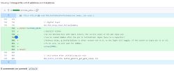
    Example of changes in a source code file with 8 additions.
    It seems to be still in place:
    https://github.com/openshwprojects/OpenBK7231T_App/blob/main/src/new_pins.c
    Can you track which commit/update breaks things for you?
    Helpful post? Buy me a coffee.
  • #20 21461561
    luudi1
    Level 9  
    Gentlemen. I have these modules in 1, 2 and 3 circuit versions. I used the 2-circuit version for the lighting in the bedroom. That is, channel one turns on one. chandelier bulb and channel two turns on the other two. Mounting the module in a flush-mounted box at the main entrance to the bedroom (incoming power, branch to the chandelier, branch to the next switch and short wires to the switch in this box).
    Generally, the system seemingly works, both via the app on the phone and via the two double short-circuit switches (double bell switches), however it happens to switch one of the circuits on or off by itself.

    I've started digging into the subject and I'm betting that the problem is controlling the neutral wire instead of the phase. I have a 5x1.5 wire laid between the boxes. And in this second distant box, between the neutral wire and the two that go to terminals S1 and S2, a phantom voltage of about 80V appears, because there is also a phase in one conductor of this multi-conductor wire (we have capacitance, two potentials separated by an insulator, i.e. a capacitor).
    Do you have any ideas how this problem can be solved?
  • #21 21461571
    p.kaczmarek2
    Moderator Smart Home
    I haven't tested this, but there was once a publication like this on Elektroda.com:
    How to fix random relay switching on BL602 IoT devices with SM-028_V1.3? .
    Original: https://www.elektroda.com/rtvforum/topic4027953.html#20904492

    Maybe this will help somehow, try it and let us know.
    Helpful post? Buy me a coffee.

Topic summary

The discussion revolves around the configuration and issues related to 2- and 3-channel WiFi flush-mount switches based on the BK7231N CB2S system, specifically the MINI-W1-2CH and MINI-W1-3CH models. Users report difficulties in reprogramming these devices using CloudCutter due to firmware limitations. Concerns are raised about safety, particularly regarding non-isolated converters and potential electrical hazards. A recurring issue is the unexpected toggling of relays upon startup, which is linked to software bugs in the firmware. Solutions include modifying the configuration settings and applying specific firmware updates from GitHub that resolve the toggling problem. Users also discuss compatibility with other devices and the importance of proper installation by qualified electricians.
Summary generated by the language model.
ADVERTISEMENT