logo elektroda
logo elektroda
X
logo elektroda

Teardown for Artika Skyshade Smart LED Panel (FLP14-SSWTR-C1WH)

ErrorGap 6003 18
ADVERTISEMENT
  • Packaging of Artika Skyshade Smart LED RGBWW.

    The Artika Skyshade is an RGBWW Smart LED Panel controlled by a CBU (BK7231N) chip.
    It can be flashed with OpenBeken and retain all the functionality of the original firmware - including the use of the Infrared remote - without the need for third-party cloud services


    On unboxing. The package comes with the LED panel, IR remote, and some mounting hardware. Per the original instructions, the panel should not be used with a hardware dimmer switch (dimming can be done via software or the remote)

    In order to flash firmware, you will need to open the panel and connect a serial cable to various points on the chip. These instructions are based on my own success re-flashing two of this device purchased late 2023 from Costco. It is possible that hardware may change in later revisions of the device.

    First, the device will need to opened in order to access the chip.
    Place the device face-down (light side down) so that the back screws and metal mounting plate are visible.

    Artika Skyshade LED panel with visible metal mounting.

    Slide off the mounting plate by pushing it against the direction of the arrow (leftward in the case of the above image)

    Next, remove all screws securing the housing, including those which hold the support-rails in place.
    Be careful not to strip anything.
    Also be careful of the metal section in the lower-left to which the power cables connect. This contains various electronics components and has additional cables which feed into the inside of the unit

    Back side of the Artika Skyshade LED panel showing screws and a metal mounting plate.

    Once you have removed the screws on either side of the metal section, you will also need to lift it out a bit and then detach the grounding screw which is attached to the power cable
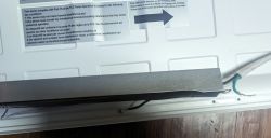
    Rear view of the Artika Skyshade LED panel with mounting instructions.

    With this done and all screws removed, you can place the support cables out of the way. Flip the inner housing of the unit around (being careful to support the metal section where the cables feed to the inside)

    On the inside, you should see the LED's with cables running into the various sections, as well as the main data+power cable running to the board containing the CBU chip

    Internal view of the Artika Skyshade LED panel showing LEDs and wiring.


    On the board, you will see:
    * a cable with connections laberlled 3v3,GND, P24, P26, P6, P7, P8
    * The CBU chip
    * An infrared sensor with some resistors
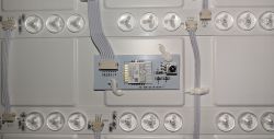
    Artika Skyshade LED panel with CBU chip and connections.

    In order to reprogram the chip, you will need to solder leads onto pins
    * 13 (PS-GRND)
    * 14 (PS-3v3)
    * 15 (TX1)
    * 16 (RX1)
    * 18 (CEN)

    Presumably you will be running these leads to a USB-TTL/UART adaptor. I have read of others having some issues with insufficient current on the 3.3v connector (and thus needing external power) but my own CP2102 adaptor seemed sufficient in this case.

    Attach leads to your chip as seen below
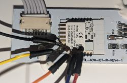
    PCB with soldered wires connected to the CBU chip.

    Close-up of a connected CBU chip in an LED panel.

    In my image
    * 13 (PS-GRND) = Black
    * 14 (PS-3v3) = Yellow
    * 15 (TX1) = Orange
    * 16 (RX1) = Blue
    * 18 (CEN) = RED (in the first picture, skip a pin from the RX connector to reach CEN)

    Also, please note that the "TX" connector would connect to the "RX" connection on your adaptor and vice-versa

    I also recommend using either a breadboard where you can easily short CEN to GRND or possible a button, as you will need to do this a few times during the flashing process

    With this in mind, connect the leads to your TTL/UART adaptor so that
    * GRND/Black = Ground
    * 3v3/Yellow = 3.3v
    * TX1/Orange = RX
    * RX1/Blue = TX
    * CEN = Initially unconnected, but easily able to short to ground

    Now fire up the "BK7231 Easy UART Flasher)

    Select the following:
    * UART port: [whatever COM your adaptor is connected to)
    * Chip Type: BK7231N
    * Firmware: Appropriate OpenBeken Firmware, I used OpenBK7231N_QIO_1.17.308 at the time
    * Baud rate: 115200 (you may go faster but I find this is a good medium for compatibility and less errors)
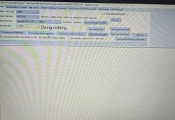
    BK7231 Easy UART Flasher screen with configuration options

    Now assuming everything is connected correctly try to "Do firmware backup (read) only". This will verify you've got a connection to the chip and dump the current firmware. Once you've hit the button in the software and entered a backup filename, briefly short the CEN pin on the chip to GRND in order to put reset the device into programming mode

    You should see progress details as the memory is read.

    Assuming that goes successfuly, next use "Do firmware write (no backup)" (this is assuming you already have a backup from the previous step and all went well). Short the CEN pin to GRND on the chip again

    The software should find the device, begin erasing sectors of the chip and then writing. When done, you should see a message
    "Writing file data to chip success"

    Your chip has now been reprogrammed. Short CEN to GRND one more time to reboot.

    With a phone or laptop, look for a WIFI AP called "OpenBK7231N_xxxxxxx". This will be the flashed device.
    Connect to this, then open a browser to http://192.168.4.1

    From here, you should be able to configure the device with Wifi credentials for your IoT network and save.
    Once you've done that, look for it on your own network and access again with a web browser at whatever IP it gets from DHCP (or static if you assigned one as such).

    If that works, you can now disconnect the pins from your serial adaptor - be careful not to short anything by accident - de-solder them from the chip, and close the device back up with all the plates, supports, and screws in place as before.

    This is it for the hardware portion. I'll cover software in the next comment.

    Added after 19 [minutes]:

    Continuing on with how to program the Artika Skyshade, here's what you need to do for the software portion of things.

    (p.s. if you haven't done so already, you should have desoldered any pins from your device, put it back together, connected to wifi and mounted it up on a ceiling somewhere with power)

    Under Config->Configure General/Flags, set the following flags: 0, 1, 8, 10, 12, 16, 22, 28
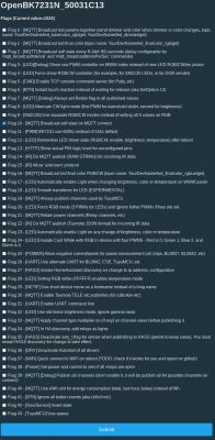
    Artika Skyshade configuration screen with various flags and setting options.

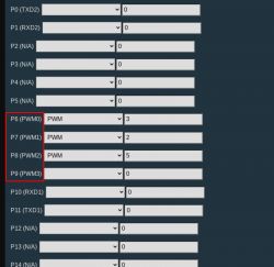
    Under Config->Configure Module
    * P6 (PWM0) = PWM 3
    * P7 (PWM1) = PWM 2
    * P8 (PWM2) = PWM 5
    * P23 (ADC3) = IRRecv
    * P24 (PWM4) = PWM_n 4
    * P26 (PWM5) = PWM 1
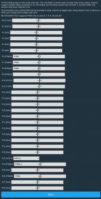
    Configuration interface for PWM settings on BK7231 chips.

    Under Config->Configure MQTT: This will need to be configured for however your own network is setup

    At this point, I recommend returning to the main menu and performing a reboot at least once, then testing that on/off functionality plus colors and warm/cold white light from the main menu on the device line up as expected

    Assuming that's all good, the last thing to do is to preconfigure some macros for the remote and then connect to your home-automation system, if any

    If you are using HomeAssistant, then go to Config->Home Assistant Configuration: CLick "Start Home Assistant Discovery" and if your MQTT settings and networking etc are all correct the device should be found automatically

    For the remote, you can hard-code functions by settings them in autoexec.bat (a filename that bring back some memories of the old DOS days)

    * From the main menu, go to "Launch Web Application"
    * Click on the "Filesystem" menu
    * Click "Create File" (name the file autoexec.bat)
    * A button for the new file should be visible, click on it
    * Enter the following into the textbox and then click "Save" (you can modify these to your preference, but they roughly match the labeled remote functionality except for 'mode' and 'favorite'

    addEventHandler2 IR_NEC 0x7E7E 0x32 led_basecolor_rgbcw #FF00000000
    addEventHandler2 IR_NEC 0x7E7E 0x1A led_basecolor_rgbcw #00FF000000
    addEventHandler2 IR_NEC 0x7E7E 0x33 led_basecolor_rgbcw #0000FF0000
    addEventHandler2 IR_NEC 0x7E7E 0x1B led_temperature 154
    addEventHandler2 IR_NEC 0x7E7E 0x30 led_nextColor
    addEventHandler2 IR_NEC 0x7E7E 0x5 power toggle
    addEventHandler2 IR_NEC 0x7E7E 0x19 add_dimmer 10
    addEventHandler2 IR_NEC 0x7E7E 0x35 add_dimmer -10
    addEventHandler2 IR_NEC 0x7E7E 0x16 add_temperature -25
    addEventHandler2 IR_NEC 0x7E7E 0x36 add_temperature 25
    addEventHandler2 IR_NEC 0x7E7E 0x18 ClearNoPingTime
    addEventHandler2 IR_NEC 0x7E7E 0x37 led_basecolor_rgbcw FF00FF0000


    Once that is saved, reboot your device once more. The code into autoexec.bat should load automatically at startup and - if successful - you should be able to point your infrared remote at the (center) of the SkyShade and trigger various functions via the buttons.

    That's it for my instructions. You should now have a light that is:
    * Reprogrammed with OpenBeken
    * Does not require any third-party cloud services
    * Is connected to your network
    * Works for various RGB colors
    * Works for varying degrees of warm/cold light
    * Is connected to your MQTT service and HomeAssistant (as applicable)
    * Works with the Infrared remote

    Cool? Ranking DIY
    About Author
    ErrorGap
    Level 5  
    Offline 
    ErrorGap wrote 8 posts with rating 14, helped 2 times. Been with us since 2023 year.
  • ADVERTISEMENT
  • #2 20882934
    p.kaczmarek2
    Moderator Smart Home
    Thank you for the guide. It looks very detailed and useful, especially for our beginners.

    With a light already configured like this, you can do multiple cool things with that, for example, you can use DGR protocol to link together lights and switches:


    You can also use it with, for example, Tasmota Control app:


    You can also enable SSDP to make device visible by Windows:


    I want to add your guide to our devices list, here: https://openbekeniot.github.io/webapp/devicesList.html , but it's still missing JSON, can you go to OBK Web App and copy JSON template here?
    Helpful post? Buy me a coffee.
  • #3 20884378
    ErrorGap
    Level 5  
    Yes, of course.
    I'm not sure what the "bDetailed" field is for but I've filled the rest

    {
      "vendor": "Tuya",
      "bDetailed": "1",
      "name": "Artika Skyshade Smart LED Panel",
      "model": "FLP14-SSWTR-C1WH",
      "chip": "BK7231N",
      "board": "CBU",
      "flags": "272700675",
      "keywords": [
        "RGBWW",
        "Panel",
        "Costco"
      ],
      "pins": {
        "6": "PWM;3",
        "7": "PWM;2",
        "8": "PWM;5",
        "23": "IRRecv;0",
        "24": "PWM_n;4",
        "26": "PWM;1"
      },
      "command": "",
      "image": "https://obrazki.elektroda.pl/8249013800_1703830959.jpg",
      "wiki": "https://www.elektroda.com/rtvforum/topic4024658.html"
    }
  • #4 20884402
    p.kaczmarek2
    Moderator Smart Home
    The bDetailed field is used to feature a detailed and well written reviews, just like yours. You fully deserve having bDetailed set to 1, I will edit your post. I will also add this teardown to our list, so now we have 458 teardowns in total.
    See: https://openbekeniot.github.io/webapp/devicesList.html

    Added after 1 [minutes]:

    One more question - is PWM_n correct there?
    If it is, then can you provide Tuya config for reference?
    https://www.youtube.com/watch?v=WunlqIMAdgw
    I am asking because I haven't seen yet Tuya JSON for device with PWM_n
    Helpful post? Buy me a coffee.
  • #5 20885988
    ErrorGap
    Level 5  
    Quote:
    is PWM_n correct there?


    If one uses just "PWM" for P24 it will mostly work, but the cold and warm light output will be opposite of what is selected on the slider.
    Use of PWM_n matches up the "cold" vs "warm" output properly.

    This device also was one that did not automatically pull the configs from the original TUYA firmware, i.e when using Easy UART Flasher during the backup process, it wasn't able to resolve this for some reason (though it did so for other devices).

    I will send the Tuya config in PM but I'm not sure it'll have the pertinent data in this case.
  • ADVERTISEMENT
  • #6 20886009
    p.kaczmarek2
    Moderator Smart Home
    Ah, I see, so there is no meaningful data in Tuya Config. Ok, this explains it a bit. I have extracted the binary file you've sent me and confirmed that. There doesn't seem to be any private data, but still, here is a censored version:
    Code: JSON
    Log in, to see the code
    Helpful post? Buy me a coffee.
  • #7 21016917
    VanMak
    Level 4  
    Thanks for this great post, I picked up two of these lights in Vancouver, Canada today and have flashed one so far. With the provided config however, Red does not work. Using the web app, Green, Blue, Warm, Cold, Brightness, Toggle all work, when I choose Red, I get a yellow instead. Kindly provide some direction as to which pin(s) I should be changing.
  • #8 21017101
    p.kaczmarek2
    Moderator Smart Home
    I think you need to change some of the channels here:
    ErrorGap wrote:

    Configuration interface for PWM settings on BK7231 chips.

    There is not much options because there is a limited number of PWMs on BK7231 chips, as you can see here:
    PWM channel configuration table for BK7231 chips.
    So, you need to methodically experiment and check which color is missing or swapped.

    Alternatively, you can try use this method to extract PWM config. It works in most cases:


    This may be faster than guessing pins.
    Helpful post? Buy me a coffee.
  • #9 21017738
    VanMak
    Level 4  
    Looks like I'll be guessing pins, I had extracted the config from the factory firmware, both that JSON and the one extracted after flashing don't provide anything useful.

    Factory:
    Sorry, no meaningful pins data found. This device may be TuyaMCU or a custom one with no Tuya config data.
    No module information found.
    And the Tuya section starts, as usual, at 2023424

    OBK:
    Sorry, no meaningful pins data found. This device may be TuyaMCU or a custom one with no Tuya config data.
    No module information found.
    And the Tuya section starts at UNCOMMON POSITION 0
  • #10 21017750
    p.kaczmarek2
    Moderator Smart Home
    Ok, but which channel is missing for you? Red? Green? Blue? Warm? Cool?
    Maybe temporarily enable this flag:
    
    3	[LED][Debug] Show raw PWM controller on WWW index instead of new LED RGB/CW/etc picker
    

    and check each of the channels?
    Helpful post? Buy me a coffee.
  • #11 21017768
    VanMak
    Level 4  
    >>21017738
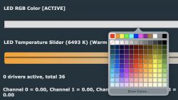
    I think I figured out the problem, and it wasn't with pin assignment. I was using this tool for testing colours:

    Color LED temperature slider and active RGB settings.

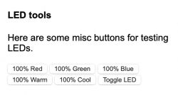
    And it produced yellow instead of red. When I used this tool however:

    Screenshot of an LED testing tool with a set of buttons for color adjustment.

    It works fine.

    EDIT: IR Receive does not work at this time however.
    Edit 2: RTFM - add autoexec.bat

    Added after 3 [hours] 8 [minutes]:

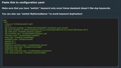
    Why, on the homeassistant configuration page, does it say to paste some text into configuration.yaml?
    Fragment of a YAML configuration file for Home Assistant with RGB LED settings.

    Does this add additional features I haven't realized I'm missing out on yet?
  • #12 21018053
    p.kaczmarek2
    Moderator Smart Home
    I am glad to hear that the color issue is resolved! You can calibrate colors later if you think they do not match well.

    Regarding HA, this copy-paste method is obsolete. You can use automatic discovery now:


    Helpful post? Buy me a coffee.
  • ADVERTISEMENT
  • #14 21385943
    Sunrise_Wakeup
    Level 2  
    Thank you so much for this guide. I picked 3 of these up at COSTCO (Canada) and have successfully reprogrammed one. This was a huge amount to learn in one day as I've never even used Home Assistant before but I've now gone from zero to odroid+open beken +sunrise alarm in one day.

    I have one issue - it's with the power button on the remote. It causes the light to flash. If you hold it too long it flashes a bunch of times and then may stay on or off depending on when you let go of the button. If you don't hold it long enough it might do nothing at all. Is there an alternative setting for addEventHandler2 IR_NEC 0x7E7E 0x5 other than "power toggle"? It seems to have almost like a debouncing type bug. For now I remapped the power button to "power off" and the colour cycle button to "power on" but maybe there's a better way? Thanks again!
  • ADVERTISEMENT
  • #15 21385944
    p.kaczmarek2
    Moderator Smart Home
    I'm not sure about IR behaviour itself, but I think we can easily come up with some simple "debouncing" method for the power command itself. I'll look into it tomorrow. That way it will execute command only on first press, ignoring futher command repeats.
    Helpful post? Buy me a coffee.
  • #16 21385960
    Sunrise_Wakeup
    Level 2  
    Very cool, thanks! I do have one other question - is there a way to make the 1% brightness even lower - basically as low as possible? It would help with the gentle wake up automation I'm trying to get working. Thanks!
  • #17 21386746
    Sunrise_Wakeup
    Level 2  
    I have now opened, reprogrammed, and reassembled three of these panels without any issues. A note about the reset pin - you can get away without soldering it, it works fairly well to just touch a ground to that pin during the process. You only need to do it once (during the test read) so it's not too onerous and saves one solder action.

    A couple assembly tips:

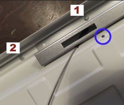
    1. There are two different sizes of screws holding the panel together, though they look very similar. Every screw that goes through a metal part (support bars or wire housing) or attaches a ground cable is a fatter screw (type 1 in photo). Every screw that passes only through the white reflector into the bezel is a smaller diameter (type 2 in photo). If you use the smaller screws in the larger holes, they won't grip (not a huge deal but I guess you could end up with a bad ground if you aren't careful). I disassembled all of the large screws first and separated them, then the small ones. Reassembly was in reverse order.

    2. It's easy to forget which screws the "safety cables" are attached to. I marked the screw location on each side with a small dot as a reminder (see circle in photo) and upon reassembly, it's easiest to install those safety cables screws before all the rest.

    (For reference, if you are looking at the back of the panel with the power on the lower left, the safety cable closest to you attaches on the third-from-right hole on the support bar. The safety cable on the far side connects on the second-from-left hole on the support bar.)

    Close-up of a panel with markings for different types of screws and a location for the safety cable.
  • #18 21386750
    p.kaczmarek2
    Moderator Smart Home
    I think there is gamma calibration feature than can be used to gain more control over brightness:
    https://github.com/openshwprojects/OpenBK7231T_App/blob/main/docs/led_gamma_control.md
    Altough, I didn't use it personally. It was submitted by a contributor.
    Helpful post? Buy me a coffee.
  • #19 21523151
    tenantpouter7l
    Level 1  
    >>21385944

    Any update on this issue? I’m having the same problem with the remote.

Topic summary

The discussion revolves around the teardown and firmware flashing of the Artika Skyshade Smart LED Panel (model FLP14-SSWTR-C1WH), which utilizes a BK7231N chip. Users share detailed instructions for opening the panel, connecting a serial cable, and flashing it with OpenBeken firmware, allowing for control without third-party cloud services. The panel is compatible with various protocols, including DGR and Tasmota, and can be configured for use with Home Assistant. Issues regarding color output, particularly with the red channel, are addressed, with suggestions for troubleshooting and pin configuration adjustments. The importance of avoiding hardware dimmer switches is also emphasized.
Summary generated by the language model.
ADVERTISEMENT