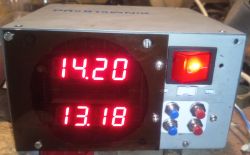
A few years ago I electrified my old Dutch bicycle. Regulation motor, regulation method of control based on detecting the rotational movement of the pedals. The principle is simple: you turn the pedals, the motor supports you a little (the level of support can be set). You don`t shoot, you don`t drive
Last summer, the power steering failed, I removed it and rode without it. But it`s winter, so I have some time to analyze the extent of the damage. Generally, I assume two possibilities: the main Chinese controller is dead (and then it fails), or my PAS sensor is dead (or making another copy is simple and cheap). In order to diagnose it, you need to feed this square wave (approx. 6-7 Hz) to one of the inputs of the main controller. I could do this using a service generator, but I decided it would be better to make a small, self-contained generator board. It will allow me to diagnose damage to the PAS sensor, but it will also serve as a backup source of the square wave signal in case my pedal sensor fails, e.g. 45 km from home. In this case, just plug in this little "device" and the bike "thinks I`m turning the pedals"
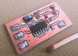
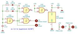
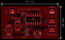
Here we have a diagram, a preview drawing of the board and the PCB with the elements themselves (Top layer). As you can see, this is a really small module.
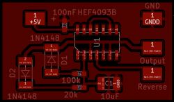
Well, today I finally launched my small but very useful project. Oscilloscope measurements showed that the results are very good, I measured a frequency of 6.4 Hz with a duty cycle of 20% on one output and 80% on the alternative output.
So I already have the test module, all I need to do is assemble the bike`s support elements and perform a diagnosis of the whole thing. I recommend this "rescue" module to everyone who has this type of drive. Controllers usually have one harness for the PAS sensor (three wires: +5V, ground and rectangular signal). In this project, we have two outputs to choose from: a signal with a 20% duty cycle and its inversion (i.e. an 80% duty cycle) - I added the second output due to different interpretations of the signal by different controller models.
If you look at the diagram, it is easy to see that by changing the 4.7uF capacitor and the values of both resistors (you can also draw potentiometers here), we will determine the frequency and filling of the rectangle we need.. So this is quite a useful diagram. The construction cost is practically non-existent.
Please don`t be picky about the photo, this time it was taken with a cell phone, and it`s a test module, so it`s a bit snotty with tin - these tests have to be done somehow. :-)
Edit:
The module has proven to be excellent in practice.
Cool? Ranking DIY


