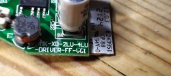
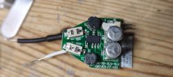
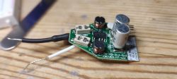
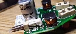
I don't see that many GU10s being opened, maybe because successfully putting them back together again can be hit and miss. I've broken a couple of live/neutral pins from the chassis before and not bothered to even attempt putting it back together.
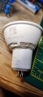
A previous semi-successful attempt saw a 4lite Wiz GU10 reveal an unknown ESP8285 module which I posted about in reply to an old thread here https://discourse.superhouse.tv/t/flashing-an-esp-8285-on-a-wiz-bulb/741/4?u=divadiow
In that attempt I cut the chassis in half so the PCB could be freed for desoldering and flashing with Tasmota. Sadly I cut in slightly the wrong place so had to cut again. The reconstruction works fine but it doesn't look nice and it's a little wonky!
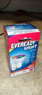
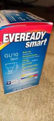
Anyway, the subject of this post is a Poundland UK GU10 RGBCCT, which costs £5 and can probably be found in the high street in most towns in the country. Their web site does not list the item.
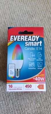
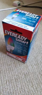
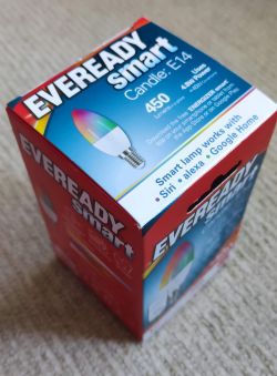
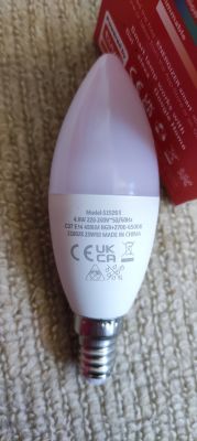
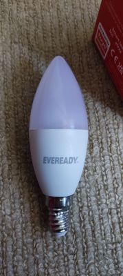
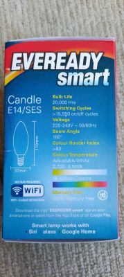
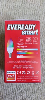
Packaging and bulb exterior
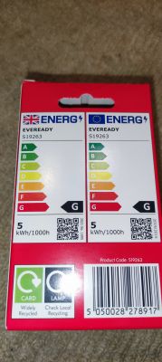
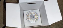
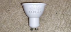
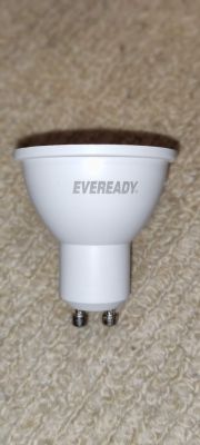
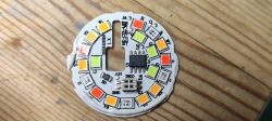
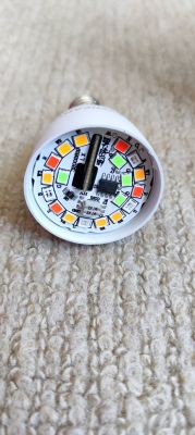
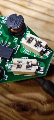
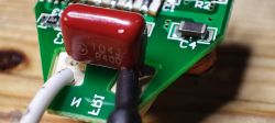
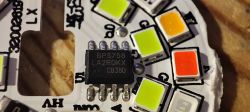
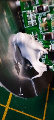
The clear Perspex cover over the LED disc is not held on very tightly, so a small craft knife was used to lift without any damage. The LED disc as usual is glued around the rim to the main body using a white silicone. I scored the very edge round with a scalpel then used a plastic scraper to remove the excess. To my surprise the disc was glued to the PCB so the whole lot lifted, pulling the wires down the live/neutral pins with it! I thought this was the end because previously this has meant pulling the wires off the PCB, breaking solder. It turns out the wires are not soldered in these bulbs, but are tightly pushed into the centre of the pins. This is good news for reconstruction.
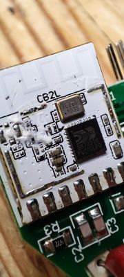
With everything free I can photograph the rest before desoldering the tiny BK7231N based CBLC5.
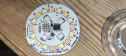
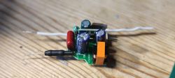
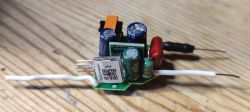
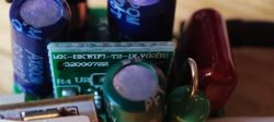
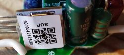
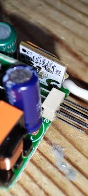
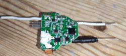
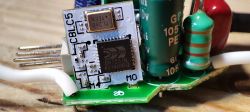
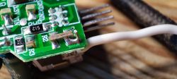
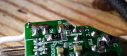
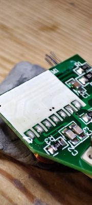
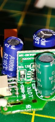
Nice. The module is not soldered in straight at the factory. I see the antenna is soldered directly to the antenna pad on the module. And interesting is the second riser board in the middle. Silkscreen "MK-BK-WIFI-T2-DLV02(B)". I do not know what this is for.
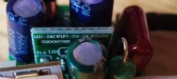
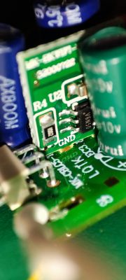
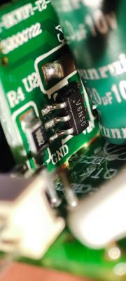
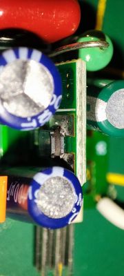
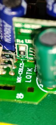
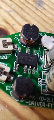
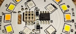
I also notice that a BP5758D is present, driving the LEDs. I know already that OpenBK has a driver for this.
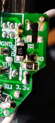
After fluxing and desoldering with copper braid, the module was free.
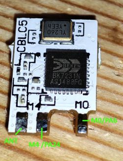
I like to make my own labelled diagrams before flashing so here they are
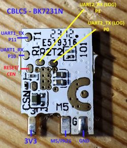
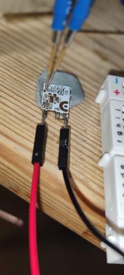
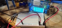
I now make a point of soldering at least the VCC and GND pins as I've killed a few chips with the ground not being connected properly with pogo pins but the power and tx/rx connected OK. I think it then grounds through the USB-TTL adaptor and kills the chip? Maybe.
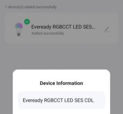
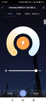
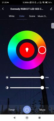
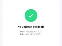
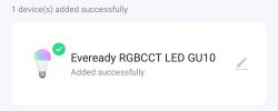
Before dumping and flashing I paired it with the Tuya app to check firmware and to see how it's recognised

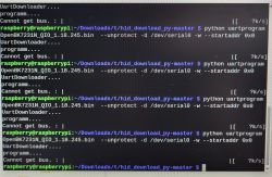
After connecting USB-TTL to UART2 TX/RX I took a log of the factory boot output.
Then after moving TX and RX pogo pins over to the UART1 pads I could use the Easy UART Flasher to take a dump of the factory firmware, attached.
Easy UART Flasher extracted the GPIO assignments from the factory firmware dump
The JSON for this
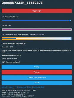
After flashing and rebooting, the AP showed as expected and the console shows the expected bulb controls
To put the unit back together I first stuck a sewing needle through the little holes on each of the power pins from the outside, to ensure the cables pushed from the inside would have every chance of at least getting part-way through. I then fluxed the ends of the wires and fed them through the inside. The black cable has a stiffer sold core so went through more easily. The white cable needed helping through with some tweezers
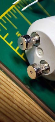
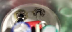
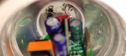
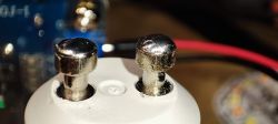
I then fluxed the ends of the outside pegs and soldered a small dome onto each. The wires seem like they've taken to the solder and are held fast. The small domes do not appear to affect the insertion or removal of the bulb from a standard GU10 holder. They can always be sanded flat a little if they do.
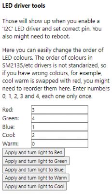
I'm pretty pleased with this journey and the end result. There is one thing not yet right - the cool-warm slider is having the opposite effect - ie the warm end makes the white LEDs cool and the cold=warm. I don't see a flag to reverse the behaviour. Perhaps it's something to do with the LED mapping. I'll explorer further.
Finally, here is OBK template and PR.
https://github.com/OpenBekenIOT/webapp/pull/82
A previous semi-successful attempt saw a 4lite Wiz GU10 reveal an unknown ESP8285 module which I posted about in reply to an old thread here https://discourse.superhouse.tv/t/flashing-an-esp-8285-on-a-wiz-bulb/741/4?u=divadiow
In that attempt I cut the chassis in half so the PCB could be freed for desoldering and flashing with Tasmota. Sadly I cut in slightly the wrong place so had to cut again. The reconstruction works fine but it doesn't look nice and it's a little wonky!

Anyway, the subject of this post is a Poundland UK GU10 RGBCCT, which costs £5 and can probably be found in the high street in most towns in the country. Their web site does not list the item.
Packaging and bulb exterior


The clear Perspex cover over the LED disc is not held on very tightly, so a small craft knife was used to lift without any damage. The LED disc as usual is glued around the rim to the main body using a white silicone. I scored the very edge round with a scalpel then used a plastic scraper to remove the excess. To my surprise the disc was glued to the PCB so the whole lot lifted, pulling the wires down the live/neutral pins with it! I thought this was the end because previously this has meant pulling the wires off the PCB, breaking solder. It turns out the wires are not soldered in these bulbs, but are tightly pushed into the centre of the pins. This is good news for reconstruction.

With everything free I can photograph the rest before desoldering the tiny BK7231N based CBLC5.


Nice. The module is not soldered in straight at the factory. I see the antenna is soldered directly to the antenna pad on the module. And interesting is the second riser board in the middle. Silkscreen "MK-BK-WIFI-T2-DLV02(B)". I do not know what this is for.


I also notice that a BP5758D is present, driving the LEDs. I know already that OpenBK has a driver for this.

After fluxing and desoldering with copper braid, the module was free.

I like to make my own labelled diagrams before flashing so here they are


I now make a point of soldering at least the VCC and GND pins as I've killed a few chips with the ground not being connected properly with pogo pins but the power and tx/rx connected OK. I think it then grounds through the USB-TTL adaptor and kills the chip? Maybe.


Before dumping and flashing I paired it with the Tuya app to check firmware and to see how it's recognised


After connecting USB-TTL to UART2 TX/RX I took a log of the factory boot output.
Code: Text
Then after moving TX and RX pogo pins over to the UART1 pads I could use the Easy UART Flasher to take a dump of the factory firmware, attached.
Easy UART Flasher extracted the GPIO assignments from the factory firmware dump
Code: Text
The JSON for this
Code: JSON
After flashing and rebooting, the AP showed as expected and the console shows the expected bulb controls

To put the unit back together I first stuck a sewing needle through the little holes on each of the power pins from the outside, to ensure the cables pushed from the inside would have every chance of at least getting part-way through. I then fluxed the ends of the wires and fed them through the inside. The black cable has a stiffer sold core so went through more easily. The white cable needed helping through with some tweezers


I then fluxed the ends of the outside pegs and soldered a small dome onto each. The wires seem like they've taken to the solder and are held fast. The small domes do not appear to affect the insertion or removal of the bulb from a standard GU10 holder. They can always be sanded flat a little if they do.

I'm pretty pleased with this journey and the end result. There is one thing not yet right - the cool-warm slider is having the opposite effect - ie the warm end makes the white LEDs cool and the cold=warm. I don't see a flag to reverse the behaviour. Perhaps it's something to do with the LED mapping. I'll explorer further.
Finally, here is OBK template and PR.
Code: JSON
https://github.com/OpenBekenIOT/webapp/pull/82
Cool? Ranking DIY


