Today, we are going to hack a ... water heater. This time, minimal soldering will be involved.
Long story short, about two years ago, I got myself a new heat pump water heater.
A heat pump heater is about 3x more efficient than an electric one, and everything is nice, except for the compressor fan. After the evening shower, it runs for another hour or two, making a rattling noise - the manufuckturer (sic!) said it is normal. A solution was to manually come to the laundry room and change the mode to electric. Then, in the morning, change it back to the heat pump, rinse, repeat, defeat the purpose. So I want it to go to electric right after the evening shower (humidity sensor) and turn back to the heat pump at about 4 am.
The heater is equipped with a CEA 2045 port for remote control*. (Note: The port has 240V pins, so be extremely cautious!) Lowes even had a cloud service to use it. Neat, eh? But they sunset it before I even got my heater. It used to work via an add-on dongle, IRIS. You can get them on eBay pretty cheap since they are of no use anymore. Not for a curious mind, though.
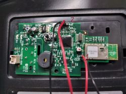
So, I got an IRIS dongle and opened it immediately. It has an IC to decode the CEA protocol and an ISM43362 Wi-Fi module from Inventeksys to send the data away. Right next to the Wi-Fi module, there are two holes for the RX and TX pins (the usual 0.1" header, marked with 1) and the 3.3V / GND pins on the 5-pin header, which is 2mm, marked with 2 (pin3 - 3.3V, pin 4 - GND, pins 1,2 show 3.3V as well, but they are not connected to the VCC pin of the wifi module - use at your own risk).

I hooked up a UART adapter (I used ESP32) to take a peek at what was going on. The config for ESP32 is below.
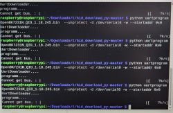
And it's alive. Initially, it tries to connect to https://energysmartwaterheater.com. This service is no longer available, so I had to add an A-record to my DNS** (I use Pihole, but it can be anything) and divert https://energysmartwaterheater.com to 192.168.0.1 (or wherever you will be hosting the bridge). But it's not so easy - now it shows an SSL error:
Luckily, there are smart people on the internet who figured it out: https://github.com/excaliburpartners/EnergySmartBridge. They provide a docker container, and everything is supposed to work from the get-go. Before you follow their instruction and build the container, read below. When they created their Docker config for the reverse proxy container, they used the nginx:latest image. The latest version then was 1.24. Now, the latest version is 1.27, which does not work anymore, so you have to go and edit their docker file in /energysmart-proxy: nginx:latest -> nginx:1.24. Then edit the config (both docker-compose.yml and EnergySmartBridge.ini) - give it the address of your MQTT broker, do docker-compose build, and docker-compose up -d. Ha, it's better now:
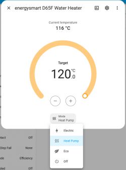
The EnergySmartBridge service sends a couple of MQTT messages reporting the status of the heater controller. Nice, but very limited. This guy (https://github.com/starsoccer/energysmartbridge) extended the bridge and unified it with a reverse proxy. I couldn't get his reverse proxy to work, so I took his source code for the bridge only (https://github.com/starsoccer/energysmartbridge/tree/master/energysmartbridge/src) and copied it to EnergySmartBridge/EnergySmartBridge, which was created following the steps here https://github.com/excaliburpartners/EnergySmartBridge . Stop all the containers created by EnergySmartBridge, delete their images, repeat the build and start procedures (don't forget to update EnergySmartBridge.ini). Now, watch the UART logs. Once it connects, you should see new topics in the MQTT explorer, particularly the "homeassistant/water_heater/C47F5101D65F/config", where you can set the configuration. Primary it defines the "mode_command_topic": "energysmart/C47F5101D65F/mode_command", and the "modes": ["eco", "heat_pump", "electric", "off"]. You can either send things directly to this topic via mosquito, or you can create a climate entry in Home Assistant: (120C is actually 120F; when I set the heater to C, it behaves strangely - I will explore more)

Now you can change the mode! Note that the dongle connects to the bridge only once every 5 minutes. So, if you change the mode in Home Assistant, don't rush to the heater to confirm; wait until the UART logs show another successful connection. Now plug it into an automation, and you're awesome! Now, you can disconnect the UART monitor.
For those who are not willing to play with Docker containers and networks, there is an alternative, more hardware-oriented way. Read the comments section, too!
* The protocol itself is RS485, but it's pretty useless without knowledge of how to decode the data. The dongle has an IC to decode it.
** I also played the router configuration to forcibly divert all traffic (especially requests to 8.8.8.8) from the dongle to 192.168.0.1. It turns out it is not necessary
Long story short, about two years ago, I got myself a new heat pump water heater.
A heat pump heater is about 3x more efficient than an electric one, and everything is nice, except for the compressor fan. After the evening shower, it runs for another hour or two, making a rattling noise - the manufuckturer (sic!) said it is normal. A solution was to manually come to the laundry room and change the mode to electric. Then, in the morning, change it back to the heat pump, rinse, repeat, defeat the purpose. So I want it to go to electric right after the evening shower (humidity sensor) and turn back to the heat pump at about 4 am.
The heater is equipped with a CEA 2045 port for remote control*. (Note: The port has 240V pins, so be extremely cautious!) Lowes even had a cloud service to use it. Neat, eh? But they sunset it before I even got my heater. It used to work via an add-on dongle, IRIS. You can get them on eBay pretty cheap since they are of no use anymore. Not for a curious mind, though.
So, I got an IRIS dongle and opened it immediately. It has an IC to decode the CEA protocol and an ISM43362 Wi-Fi module from Inventeksys to send the data away. Right next to the Wi-Fi module, there are two holes for the RX and TX pins (the usual 0.1" header, marked with 1) and the 3.3V / GND pins on the 5-pin header, which is 2mm, marked with 2 (pin3 - 3.3V, pin 4 - GND, pins 1,2 show 3.3V as well, but they are not connected to the VCC pin of the wifi module - use at your own risk).

I hooked up a UART adapter (I used ESP32) to take a peek at what was going on. The config for ESP32 is below.
Spoiler:
esphome:
name: esphome-water_heater
friendly_name: Water Heater
platform: esp32
board: esp32doit-devkit-v1
# Enable logging
logger:
level: VERBOSE
baud_rate: 0
# Enable Home Assistant API
api:
ota:
wifi:
ssid: "mySSID"
password: "myPassword"
use_address: 192.168.0.30
ap:
ssid: "Water Heater Fallback Hotspot"
password: "0zr7bHSn1epQ"
web_server:
port: 80
uart:
id: my_uart
tx_pin: GPIO1
rx_pin: GPIO3
baud_rate: 115200
debug:
direction: BOTH
dummy_receiver: true
after:
delimiter: "\n"
sequence:
- lambda: UARTDebug::log_string(direction, bytes);
And it's alive. Initially, it tries to connect to https://energysmartwaterheater.com. This service is no longer available, so I had to add an A-record to my DNS** (I use Pihole, but it can be anything) and divert https://energysmartwaterheater.com to 192.168.0.1 (or wherever you will be hosting the bridge). But it's not so easy - now it shows an SSL error:
Spoiler:
[06:00:33][D][uart_debug:158]: <<< "[BOOT AC] Enabled\r\n"
[06:00:33][D][uart_debug:158]: <<< "[JOIN ] mySSID"
[06:00:40][D][uart_debug:158]: <<< ",192.168.0.12,0,0\r\n"
[06:00:40][D][uart_debug:158]: <<< "\r\n"
[06:00:40][D][uart_debug:158]: <<< " ____ __ __ _ _____ _\r\n"
[06:00:40][D][uart_debug:158]: <<< " ___ / ___| \\ \\ / /(_)| ___|(_)\r\n"
[06:00:40][D][uart_debug:158]: <<< " / _ \\\\___ \\ _____\\ \\ /\\ / / | || |_ | |\r\n"
[06:00:40][D][uart_debug:158]: <<< " | __/ ___) ||_____|\\ V V / | || _| | |\r\n"
[06:00:40][D][uart_debug:158]: <<< " \\___||____/ \\_/\\_/ |_||_| |_|\r\n"
[06:00:40][D][uart_debug:158]: <<< "\r\n"
[06:00:40][D][uart_debug:158]: <<< " Inventek Systems\r\n"
[06:00:40][D][uart_debug:158]: <<< " Embedding Connectivity Everywhere\r\n"
[06:00:41][D][uart_debug:158]: <<< " Copyright (c)2011-2013\r\n"
[06:00:41][D][uart_debug:158]: <<< "\r\n"
[06:00:41][D][uart_debug:158]: <<< "> \r\n"
[06:00:41][D][uart_debug:158]: <<< "C4:7F:51:01:D6:5F\r\n"
[06:00:41][D][uart_debug:158]: <<<
"ISM43362-M3G-L44,C2.4.0.3.AO7,v2.4.0,v1.4.0.rc1,v7.1.0,120000000,energySmart
eS-WiFi FW-3.1\r\n"
[06:00:41][D][uart_debug:158]: <<<
"mySSID,myPASSWORD,3,1,0,192.168.0.12,255.255.255.0,192.168.0.5,255.255.255.255,255.255.255.255,2,1,0,US,1\r\n"
couple stings omitted
[06:02:45][D][uart_debug:158]: <<< "> \r\n"
[06:02:45][D][uart_debug:158]: <<< "[TCP SSL] Connecting to 192.168.0.1\r\n"
[06:02:45][D][uart_debug:158]: <<< "[TCP SSL] Validation Failure: 0C\r\n"
[06:02:45][D][uart_debug:158]: <<< "[TCP SSL] Advanced context, failed to connect\r\n"
[06:02:45][D][uart_debug:158]: <<< "ERROR: Unknown Error\r\n"
[06:02:45][D][uart_debug:158]: <<< "Usage: P6 <0 = Stop, 1 = Start> \r\n"
[06:02:45][D][uart_debug:158]: <<< "> \r\n"
Luckily, there are smart people on the internet who figured it out: https://github.com/excaliburpartners/EnergySmartBridge. They provide a docker container, and everything is supposed to work from the get-go. Before you follow their instruction and build the container, read below. When they created their Docker config for the reverse proxy container, they used the nginx:latest image. The latest version then was 1.24. Now, the latest version is 1.27, which does not work anymore, so you have to go and edit their docker file in /energysmart-proxy: nginx:latest -> nginx:1.24. Then edit the config (both docker-compose.yml and EnergySmartBridge.ini) - give it the address of your MQTT broker, do docker-compose build, and docker-compose up -d. Ha, it's better now:
Spoiler:
[06:04:26][D][uart_debug:158]: <<< "[TCP SSL] Connecting to 192.168.0.1\r\n"
couple stings omitted
[06:04:27][D][uart_debug:158]: <<< "HTTP/1.1 200 OK\r\n"
[06:04:27][D][uart_debug:158]: <<< "Server: Mono-HTTPAPI/1.0\r\n"
[06:04:27][D][uart_debug:158]: <<< "Date: Fri, 07 Jun 2024 06:04:27 GMT\r\n"
[06:04:27][D][uart_debug:158]: <<< "Content-Length: 15\r\n"
[06:04:27][D][uart_debug:158]: <<< "Keep-Alive: timeout=15,max=100\r\n"
[06:04:27][D][uart_debug:158]: <<< "\r\n"
[06:04:27][D][uart_debug:158]: <<< "{\"Success\":\"0\"}\r\n"
[06:04:27][D][uart_debug:158]: <<< "OK\r\n"
The EnergySmartBridge service sends a couple of MQTT messages reporting the status of the heater controller. Nice, but very limited. This guy (https://github.com/starsoccer/energysmartbridge) extended the bridge and unified it with a reverse proxy. I couldn't get his reverse proxy to work, so I took his source code for the bridge only (https://github.com/starsoccer/energysmartbridge/tree/master/energysmartbridge/src) and copied it to EnergySmartBridge/EnergySmartBridge, which was created following the steps here https://github.com/excaliburpartners/EnergySmartBridge . Stop all the containers created by EnergySmartBridge, delete their images, repeat the build and start procedures (don't forget to update EnergySmartBridge.ini). Now, watch the UART logs. Once it connects, you should see new topics in the MQTT explorer, particularly the "homeassistant/water_heater/C47F5101D65F/config", where you can set the configuration. Primary it defines the "mode_command_topic": "energysmart/C47F5101D65F/mode_command", and the "modes": ["eco", "heat_pump", "electric", "off"]. You can either send things directly to this topic via mosquito, or you can create a climate entry in Home Assistant: (120C is actually 120F; when I set the heater to C, it behaves strangely - I will explore more)

Now you can change the mode! Note that the dongle connects to the bridge only once every 5 minutes. So, if you change the mode in Home Assistant, don't rush to the heater to confirm; wait until the UART logs show another successful connection. Now plug it into an automation, and you're awesome! Now, you can disconnect the UART monitor.
For those who are not willing to play with Docker containers and networks, there is an alternative, more hardware-oriented way. Read the comments section, too!
* The protocol itself is RS485, but it's pretty useless without knowledge of how to decode the data. The dongle has an IC to decode it.
** I also played the router configuration to forcibly divert all traffic (especially requests to 8.8.8.8) from the dongle to 192.168.0.1. It turns out it is not necessary
Cool? Ranking DIY


