 .
.
The topic of changing the firmware of IoT devices comes up all the time on the forum, but not everyone knows the purpose of doing such a thing. Here I will present one of the advantages of freeing our device from the cloud, namely the possibility of significantly extending its functionality and even with things that the manufacturer never thought of. All on the original Chinese WiFi chip from the middle! But from the beginning...
Used device .
For the presentation I am using an RGBCW lamp given to me by a reader from Germany. I have discussed this lamp itself in the topic:
Reverse engineering and commissioning an LED lamp on the SM15155 chip (similar to WS2812B), datasheet .
Just a quick reminder here that this lamp has no button, you just control it normally with your phone.... The lamp already has OpenBeken uploaded:
https://github.com/openshwprojects/OpenBK7231T_App
Which was uploaded with our flasher via UART:
https://github.com/openshwprojects/BK7231GUIFlashTool
With the basics out of the way, we move on to the fun stuff.
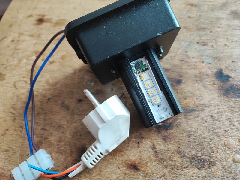
Current status of the lamp: the lamp has OpenBeken uploaded on BK7231N, works fine with HA, you can control colours, etc:
 .
.
... although the fact is that there is no lampshade. I can't help it, the reader sent it to me without one.
Wire routing .
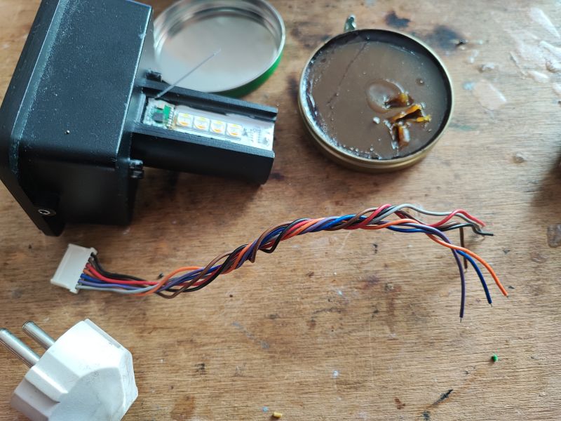
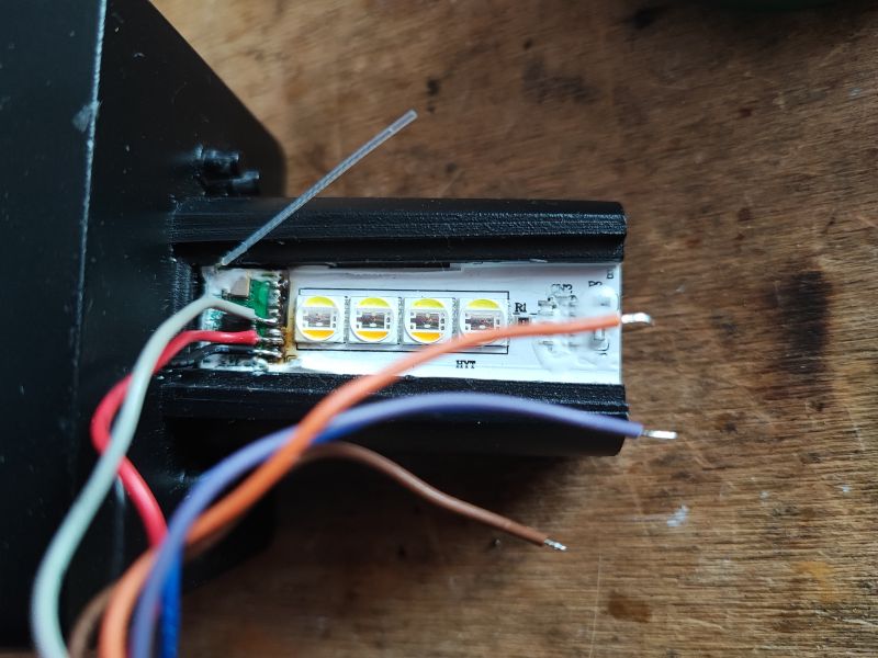
In the previous topic about this lamp, I desoldered its WiFi module in order to, among other things, read the markings of its pads. I now know where which signal is routed out. The lamp itself only uses one pin (from P16, that's the SPI hardware data output) to control a WS2812B style LED controller. The rest of the pads are free and can be used....
That being said, I'm reaching for the scrap cables, time to whittle and solder them:
 .
.
Done, I also checked everything for short circuits, there are none:
 .
.
This way we get ground, 3.3V power supply and 5 scriptable GPIOs.
First tests .
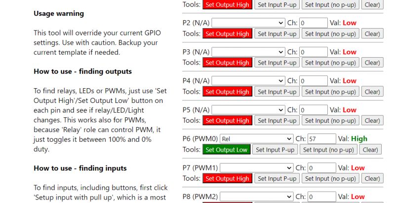
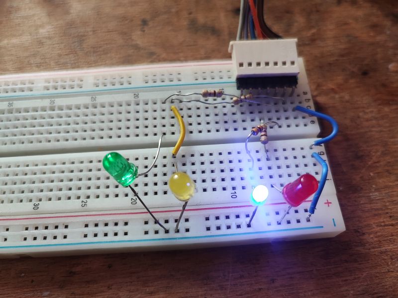
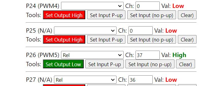
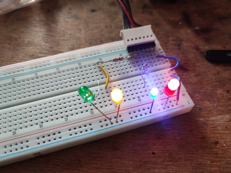
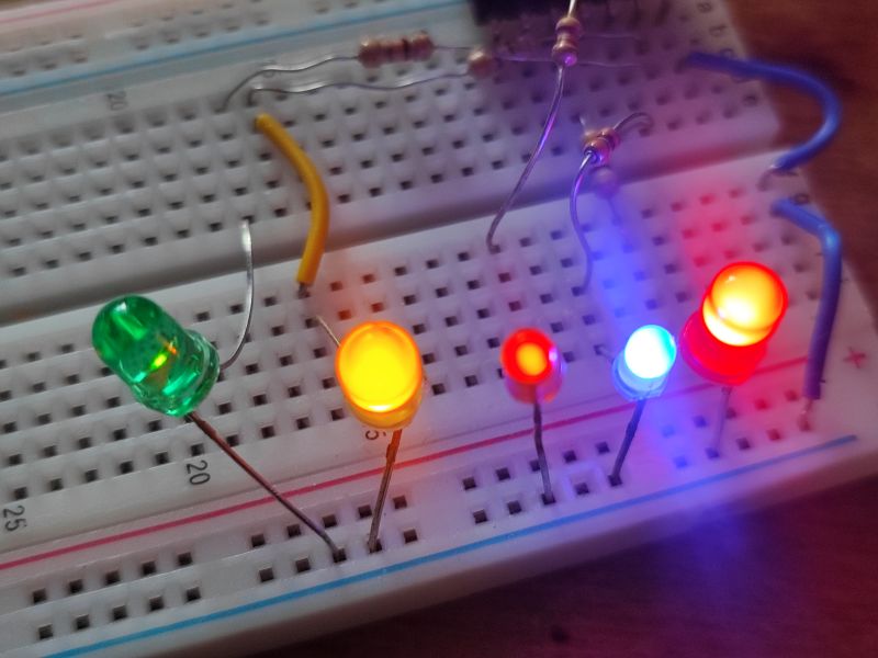
To start with something simple - LEDs. I connected these five LEDs, each with a suitable resistor, I had 0.47k on hand. I will test their operation using the GPIODoctor tool from OpenBeken. This tool allows you to quickly test all available GPIOs as inputs or outputs.
P6 is the blue LED:
 .
.
 .
.
P26 yellow:
 .
.
 .
.
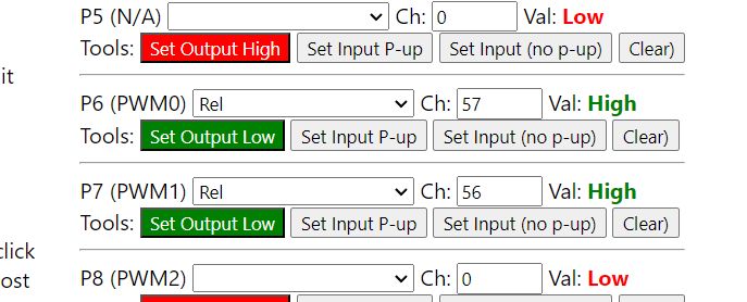
P7 red:
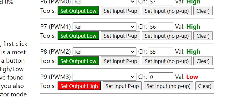
P8 orange:
 .
.
 .
.
P24 green (yes, I had it wired wrong):
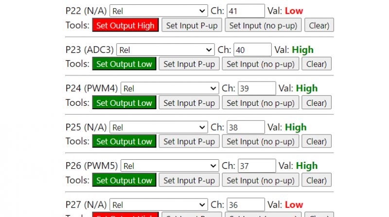 .
.
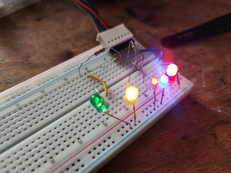 .
.
Equipped with this knowledge, we can assign them one of the many ready-made GPIO roles supported by OBK:
https://github.com/openshwprojects/OpenBK7231T_App/blob/main/docs/ioRoles.md
Or simply write our own driver in C:
How to create a custom driver for OpenBeken using online compilation .
Add a button .
OpenBeken offers many predefined GPIO roles that work as soon as they are configured, and this lamp did not normally have a button, making it useless without a phone. We can change this.
We connect the button to the selected GPIO. No resistor is needed as the BK7231 has internal configurable pull-up resistors:
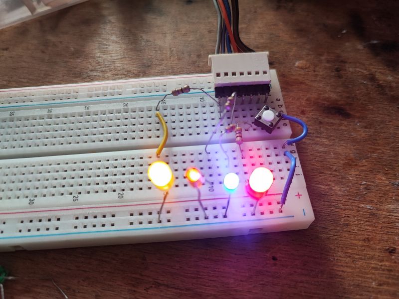 .
.
Then you can start by testing in GPIO Doctor if everything works:
 .
.
 .
.
After that, you can normally in the GPIO roles assign for the selected GPIO one of the predefined roles for LED lamps, preferably Btn_SmartLED:
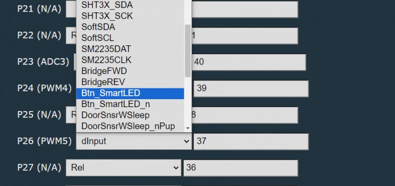 .
.
Test (click):
We test (press):
We test (double-click):
I think I need to improve the response times (there is a command for this), because I press too fast....
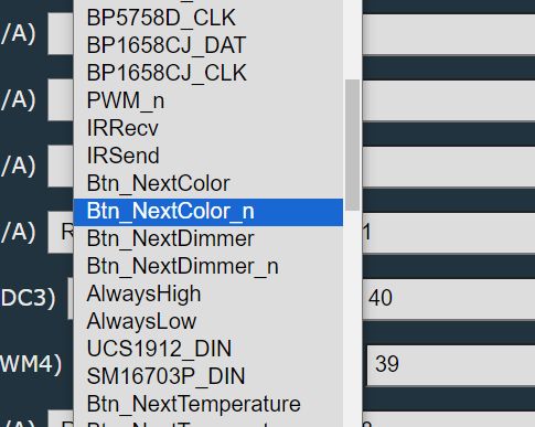
Of course, typing everything under one button might not be convenient - that way we also have separate roles, e.g. Btn_NextColor , but then you need more buttons.
 .
.
DHT11 sensor .
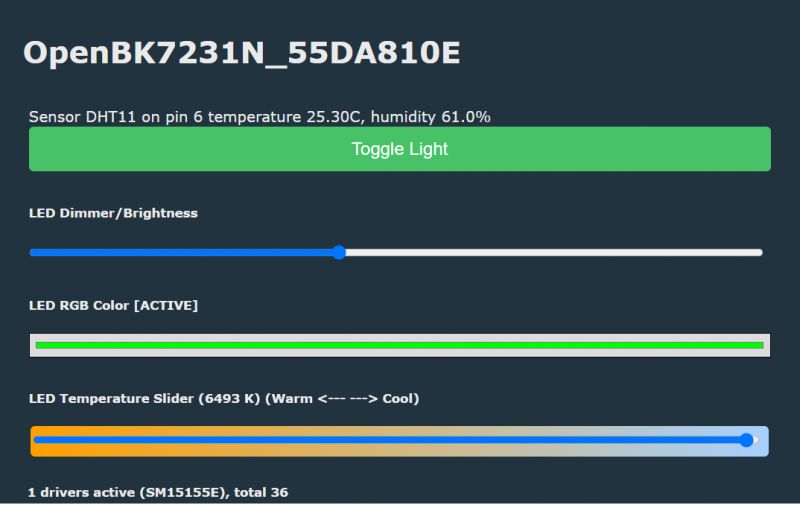
It's time for something more ambitious. Now we'll connect the DHT11 temperature and humidity sensor. Let's pick a pin, say P6:
 .
.
In addition to the pin, you need to enter the channels in which the results will be stored. If we have a relay on a channel, for example, we skip that index and enter the next one.
And that's it, everything works:
 .
.
After performing Home Assistant Discovery, these results will also be in HA.
IR receiver .
The IR receiver has already been presented, I will not repeat it here:
<spanclass="notranslate"> Display .
The presented firmware also supports a large number of different LED displays (or more precisely their drivers), including TM1637, TM1638, HT16K33, HD2015, etc, full list here:
https://github.com/openshwprojects/OpenBK7231T_App/blob/main/docs/drivers.md
I had a TM1637 on hand, time to get it working. I selected the pins:
- P24 - CLK
- P8 - DIO
 .
.
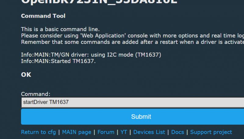
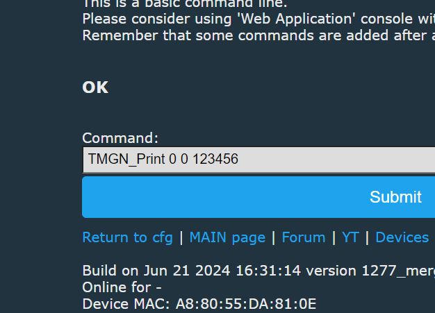
Now all you need are a few commands, the documentation is here:
https://github.com/openshwprojects/OpenBK7231T_App/blob/main/docs/commands.md
Some drivers may not be included in the public binary files, but this was explained in the topic:
System online builds OpenBeken - firmware compilation for all platforms on Github .
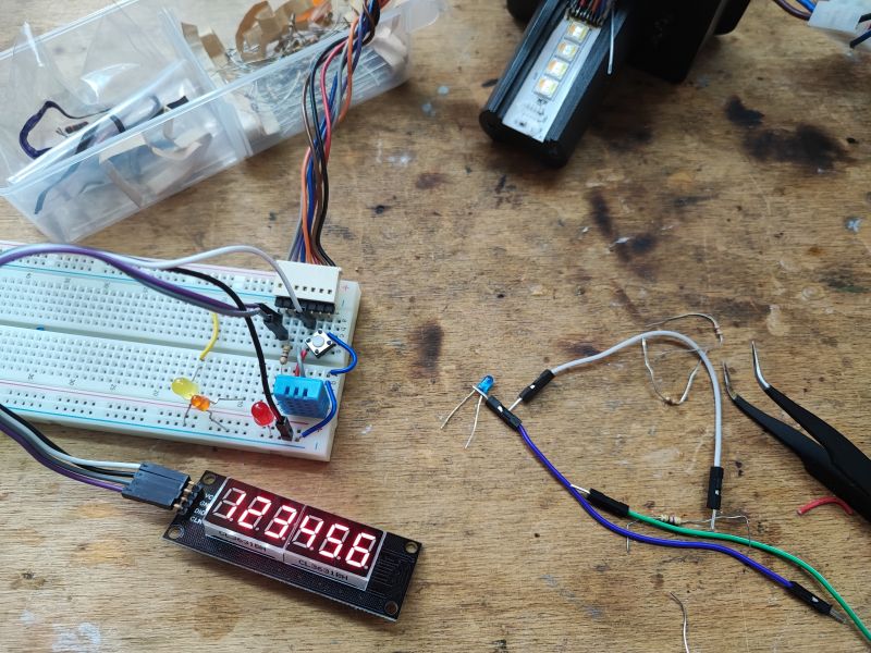
Fire up and display:
 .
.
 .
.
Result:
 .
.
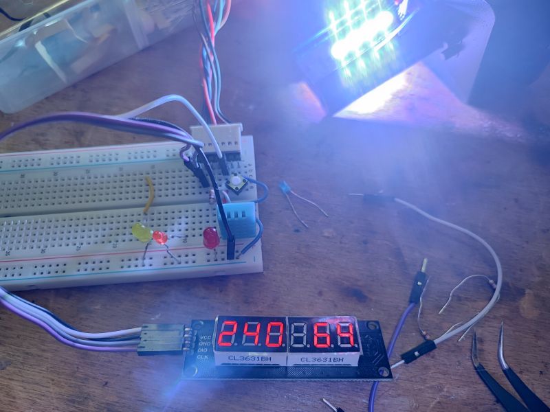
However, that is not all. The firmware also has the seed of a scriptable system allowing, for example, commands to display measurements from the DHT11. Here is an example:
backlog TMGN_Clear; TMGN_Print 0 0 $CH1; TMGN_Print 4 0 $CH2
Result:
 .
.
Separately, there is also a TextScroller driver for scrolling text (compatible with various displays), so you could add a dot and markings (e.g. letter C and H), but this is just an example, so that's enough.
And if we need quirks, you can always read the topic:
How to create a custom driver for OpenBeken using online compilation .
Summary .
Changing the firmware of an IoT device brings various benefits, here I have focused on one of them. After uploading the OBK on the BK7231 in a light from China, I got a de facto customisable "sandbox" to which various buttons, sensors, etc. can be connected, as well as being able to then easily pair with the Home Assistant via HASS Discovery. These measurements from the DHT11 can also be easily accessed in the HA.
In this way we can expand the functionality of our device, both by basic things ( how can a manufacturer sell lamps without physical buttons! What kind of nonsense is this? So if I lose my phone or if my router goes down, I can't turn this light off anymore? In my opinion, this is unacceptable... ), as well as for variety, such as DHT11 or there even BME280 (also supported).
That's it for now for this presentation. Now I only have one dilemma - what can I ultimately do with this lamp? The reader sent it to me without a lampshade, what will I fit to it to make it look and stick somehow? Does anyone have any ideas?
Cool? Ranking DIY Helpful post? Buy me a coffee.


