logo elektroda
logo elektroda
X
logo elektroda

System for 1 USD * - TV remote control by piotr_go

piotr_go 9846 68
ADVERTISEMENT
Treść została przetłumaczona polish » english Zobacz oryginalną wersję tematu
  • System for 1 USD * - TV remote control by piotr_go

    Hello, after a long break. This time the Chinese ... chip from Taiwan was used to build an IR remote for TV from LG.
    The remote control can turn on / off the TV, change the channel or the volume. The number of functions has been limited due to the small number of IO of the microcontroller.
    The used PFS154 can be changed to PMS150C after a slight modification of the program.

    Codes:
    To find out how the original remote control works, I connected an analyzer to its transmitting diode.
    The pilot transmits at a frequency of 38 kHz. First there is a longer start bit, then 8 data bits + the same 8 bits only inverted, then another 8 data bits + negated 8 bits, finally a short stop bit.
    Holding the key down causes sending a slightly different start bit every 100 ms without additional data.

    The frequency of 38 kHz is generated by software:
    Code: AVR assembler
    Log in, to see the code


    Similarly with "emptiness":
    Code: AVR assembler
    Log in, to see the code


    In the "a" register, the signal length.

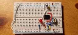
    Diagram:
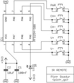
    System for 1 USD * - TV remote control by piotr_go

    I gave up the diode current limiting resistor :P .
    The current capacity of the pin at a short-circuit to plus 3.3 V is 24 mA (measured).


    * in before covidowo / wojnej currency, 2019 BC (before covid)

    Cool? Ranking DIY
    About Author
    piotr_go
    DIY electronics designer
    Offline 
    piotr_go wrote 2838 posts with rating 3188, helped 91 times. Been with us since 2003 year.
  • ADVERTISEMENT
  • #2 20110887
    Anonymous
    Level 1  
  • #3 20110914
    piotr_go
    DIY electronics designer
    spec220 wrote:
    It is a bit not professional to load the pin of the microcontroller with a current exceeding 20 mA

    The Chinese like to connect 7-segment displays without resistors. These microcontrollers have a programmable IO current capacity.

    spec220 wrote:
    Connecting such an LED directly to the 3.3V line will simply burn it

    IR LEDs consume quite a lot of current> 20 mA
    If I counted correctly, at 3.3 V it will be something like 16 mA. So that the stock is there.
  • #4 20110955
    ArturAVS
    Moderator
    piotr_go wrote:
    The Chinese like to connect 7-segment displays without resistors.

    But they have very bright displays that even hit the eyes at a few mA. Beautiful tomcat. :D
  • #5 20110970
    piotr_go
    DIY electronics designer
    ArturAVS wrote:
    But they have very bright displays that are already at a few mA

    What on the common anode / cathode gives ...

    I would not connect to AVRk like that. Apparently you can.
  • ADVERTISEMENT
  • #6 20110990
    NegativeFeedback
    Level 15  
    Well, in fact, such a 'you can because you can', but I have also done such recently, one of the thermometers will flash the temperature with green and red LEDs, and red blinking non-stop when it is 30 ° C. And recently it is also an anti-screensaver, every 10 minutes it 'presses' the Num Lock key. Both are equally useful I think :) Both on MSP430.

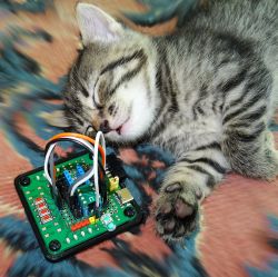
    ps red paws and snout fall, sweetheart after the hunt?
  • #7 20111023
    piotr_go
    DIY electronics designer
    Out of curiosity, maybe I will test how much they can withstand a short circuit.
    I used to tire 3V Chinese ARM above 7V. It didn't die, it just turned off. Until 7 V, he walked normally, he did not even heat up.

    NegativeFeedback wrote:
    after a hunt?

    2 they are one hunted for the other.
    Several times I saw them asleep with their eyes open. :)
  • #8 20111049
    Anonymous
    Level 1  
  • #9 20111061
    piotr_go
    DIY electronics designer
    spec220 wrote:
    16 mA it would be if some limiting resistor were used in the US.

    I would not expect a built-in current source from a 3 cent chip.
    16mA after taking into account the decrease in the LED, 24 mA without the LED.
    Although I admit that I did not measure with the LED. I'll check in a minute and let you know.


    Added after 22 [minutes]:

    OK, I admit without hitting, 23 mA with LED. I did not expect. Good to know. In PDFs I usually see a voltage dependent value. Hence my mistake.
    But I also "made a mistake" with the LEDs. TME apparently gives the test value instead of the nominal one (test value 20 mA, nominal 50 mA, impulse current up to 1.2 A).

    Added after 41 [minutes]:

    And one more test. When powered by 5V, the current on the 40mA pin, with and without LED.

    Short circuit current sink on:
    PA0 55 mA
    PA3 55 mA
    PA4 55 mA
    PA5 40 mA
    PA6 36 mA
    PA7 36 mA

    Short-circuit current source on:
    PA0 44 mA
    PA3 44 mA
    PA4 44 mA
    PA5 0 mA (I did not break it, it's the reset pin)
    PA6 44 mA
    PA7 44 mA

    Tested chip: PFS154.
  • #10 20111164
    Anonymous
    Level 1  
  • ADVERTISEMENT
  • #11 20111189
    piotr_go
    DIY electronics designer
    IO current can be set to normal, low and pull-up.
    I only measured normal.
  • #12 20111199
    Anonymous
    Level 1  
  • #13 20111238
    piotr_go
    DIY electronics designer
    My guess is there must be more than a single transistor shown in the PDF.
  • #14 20111298
    Anonymous
    Level 1  
  • #15 20111404
    piotr_go
    DIY electronics designer
    I tired PA5 set to 0 and shorted to +.
    After an hour on 3.3V and 5V power supply. The short-circuit current is still as it was.
  • #16 20111436
    Anonymous
    Level 1  
  • ADVERTISEMENT
  • #17 20111674
    Mlody_Zdolny
    Level 30  
    The PFS154 just has a global setting for all Low / Normal current output pins, something like fuses in the AVR.
    In PFC460, individual Normal / Strong pins can be individually set in a dedicated IOHD register.
    There is hardly any Vref involved in the current limiting. Most likely this is done with two parallel end stages toggled on and off with Code or IOHD.
  • #18 20111701
    piotr_go
    DIY electronics designer
    spec220 wrote:
    If there was the same mA at short circuit for 3.3V and for 5V

    Same as an hour ago. Nothing has fallen.

    spec220 wrote:
    For example, in AVR you have the choice of an internal source, or, more precisely, an external one

    I will emphasize right away that I do not know the newer AVRs very much.
    In AVR, is this internal reference used for IO? It eats up a lot of electricity. Some link maybe because I got lost.
    In older ones, I associate the tables with the IO current depending on the power supply.
  • #19 20111936
    Anonymous
    Level 1  
  • #20 20111970
    Mlody_Zdolny
    Level 30  
    spec220 wrote:
    maintain a stable parameter

    Where do you say that this is a stable parameter?
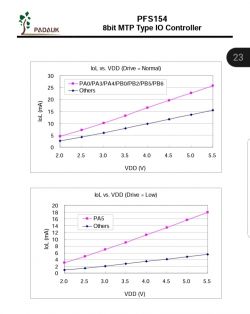
    The Iout characteristic as a function of Vcc is almost the resistor characteristic.

    System for 1 USD * - TV remote control by piotr_go

    It is enough to connect the end stages with the appropriate transistors.

    System for 1 USD * - TV remote control by piotr_go
  • #21 20112230
    Anonymous
    Level 1  
  • #22 20112297
    piotr_go
    DIY electronics designer
    @ spec220
    I will repeat again. After an hour, the current was the same as at the beginning of the test, not the same for 5V as 3.3V.
    What is this internal / external reference in the AVRs about? Any link maybe?
  • #23 20112342
    Anonymous
    Level 1  
  • #24 20112350
    ArturAVS
    Moderator
    spec220 wrote:
    Generally, I connect Vrev to + Uz US through the LC filter.

    You pin it voltage reference input for ADC which has nothing to do with the outputs. For the outputs, no Vref is needed (because why the hell should ADC be involved in it?), Here, as a last resort, factory calibrated current sources are enough, where the reference resistor is switched accordingly depending on the requirements.
  • #25 20112372
    Anonymous
    Level 1  
  • #26 20112379
    BOOM i ZONK
    Level 21  
    Well, it does NOT stabilize its current! The current depends on the VCC. It is the internal resistance of the PULL-UP transistor (s) that limits the current.
  • #27 20112387
    Anonymous
    Level 1  
  • #28 20112388
    piotr_go
    DIY electronics designer
    spec220 wrote:
    piotr_go wrote:
    I will repeat again. After an hour, the current was the same as at the beginning of the test, not the same for 5V as 3.3V.

    Approx. But you wrote that at the same voltage, the current was the same with the LED and directly to + Uz

    I don't think we understood each other. :)
    The "sink" current was dependent on the microcontroller VCC and not on the voltage on the IO (VCC - V_LED) which surprised me. I was expecting a decline.
    I have never used an IO as a current source before.

    spec220 wrote:
    I don't have a link, but a compiler that gives you this option.
    Generally, I connect Vrev to + Uz US through the LC filter.

    This, as ArturAVS wrote, is for ADC / comparator. Nothing to do with IO.

    BOOM i ZONK wrote:
    The current depends on the VCC. It is the internal resistance of the PULL-UP transistor (s) that limits the current.

    There is a stabilization dependent on VCC. At least that's how it turns out in tests.
  • #29 20112397
    Anonymous
    Level 1  
  • #30 20112407
    piotr_go
    DIY electronics designer
    You wrote about internal reference in AVRs for outputs so I was surprised.

    spec220 wrote:
    if an ordinary voltage divider will serve as Vrev ...

    And it probably is.

Topic summary

The discussion revolves around the development of an IR remote control for LG TVs using a microcontroller (PFS154) sourced from Taiwan. The remote can perform basic functions such as power on/off, channel changing, and volume control, although its capabilities are limited due to the microcontroller's I/O constraints. The participants analyze the current limitations of the IR LED, discussing the importance of not exceeding 20 mA to avoid damage. They also explore the microcontroller's programmable I/O current settings and the implications of using different voltage levels. The conversation includes technical details about the signal transmission protocol, current measurements, and the potential for using alternative microcontrollers like PMS150C. Additionally, there are inquiries about sourcing microcontrollers and programming methods for the project.
Summary generated by the language model.
ADVERTISEMENT