logo elektroda
logo elektroda
X
logo elektroda

How do I free the PJ-MGW1103 energy meter from the cloud and connect it to Home Assistant?

p.kaczmarek2 4371 34
ADVERTISEMENT
Treść została przetłumaczona polish » english Zobacz oryginalną wersję tematu
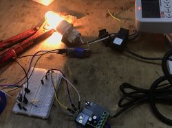
  • Test setup with a current meter and a lit bulb
    I invite you to analyse a current/voltage/power meter working normally with the Tuya ecosystem. Here I'll test it with the manufacturer's app, analyze its MCU communication protocol with the WiFi module, and then try to change it's batch to OpenBeken, which I'll configure accordingly for this purpose.

    But first....

    Related topics
    This device is based on TuyaMCU, ie. inside there is separately a WiFi module (here on BK7231N) and separately an MCU that communicates with it via UART. I will not discuss the basics of the TuyaMCU here, as I have already cited them in these topics:
    TuyaMCU protocol - communication between microcontroller and WiFi module
    TuyaMCU analyzer -. UART packet decoder for Tuya devices - dpID detector
    Flashing guide, installation and configuration of TuyaMCU - configure dpID for Home Assistant I recommend reading these before reading the content below.

    Purchase, kit contents, First impression The whole set costs about £120, depends where you buy:
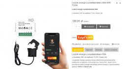
    80A WiFi energy meter with TUYA app.
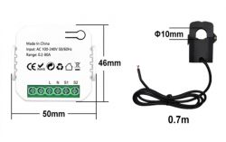
    Dimensions:
    Current meter with dimensions labeled and measurement cable
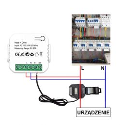
    Mounting:
    Power meter connection diagram with distribution board
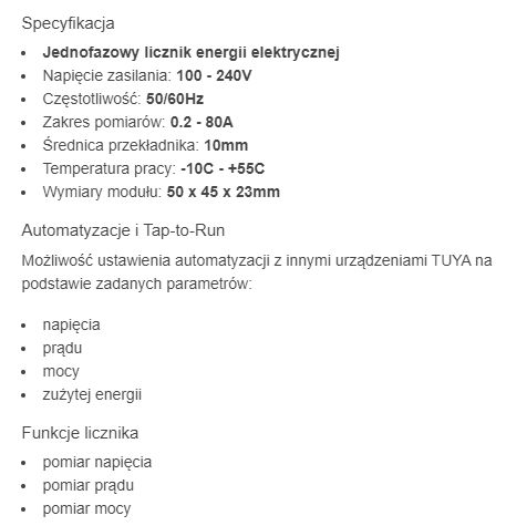
    Specification:
    Tuya electric energy meter specifications.
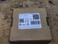
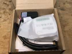
    In practice you get a box like this:
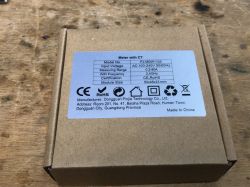
    Box containing PJ-MGW1103 energy meter Box of the PJ-MGW1103 power and voltage meter with a specification label on top.
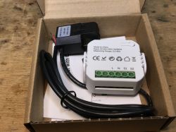
    Contents:
    Measuring device in a box. Current and voltage meter in a box.
    This time I'm not uploading the firmware straight away, but I'll start by looking inside anyway...

    Interior of PJ-MGW1103
    We remove the cover:
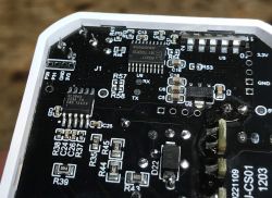
    Close-up of a circuit board with visible electronic components, including the BL0942 chip. Interior of the PJ-MGW1103 device with electronic components.
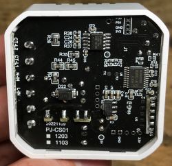
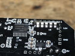
    Inside you can see BL0942 for energy measurement, but it is connected not to the WiFi module, but to a nearby MCU - here STC 381-TSSOP20 8G1K17.
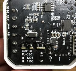
    Close-up of the PCB of the PJ-CS01 device with visible electronic components.
    Platform designation:
    20221109
    PJ-CS01
    [] 1203
    [] 1103
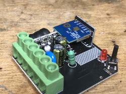
    Face-to-face view:
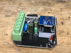
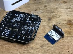
    View of the interior of the PJ-MGW1103 device with electronic modules and components. Close-up of a circuit board with a soldered electronic module and LED.
    You can see the free space after the relay, this product does not have a relay, it just performs the measurement.
    The WiFi module here is CB2S, it is based on BK7231N:
    7b21879a. CB2S WiFi module with BK7231N chip on a circuit board Close-up of electronic module with wires and components
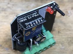
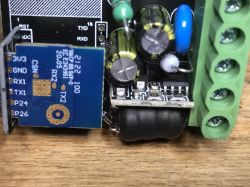
    You can also see the KP3210SG module soldered transversely into the main PCB here.
    KP3210SG datasheet - PWM switch
    This means we have a non-isolated inverter here:
    Typical application circuit diagram featuring KP3210SG.

    Test with Tuya application
    Intercepting TuyaMCU communications is discussed in the separate topic mentioned at the beginning. The whole process requires a high degree of care, as you cannot simply connect the UART from this device to our computer, there is then a risk of a short circuit. However, it is possible to use galvanic isolation for the UART, there are various modules available for purchase for this on the web.
    The process requires two USB to UART converters, as we are tapping both TX->RX and RX->TX (two lines), the whole thing is about performing operations in the Tuya application and watching what happens.
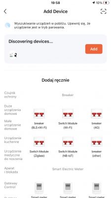
    So we start with the pairing:
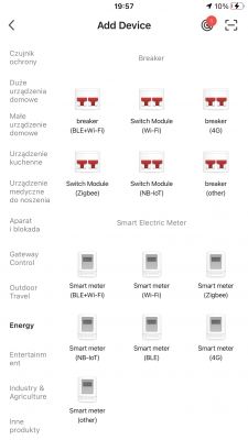
    App screen for adding devices with various smart meter options. App screen for pairing Tuya devices.
    Thanks to Bluetooth you don't even have to manually pair like in the days of ESP, the phone detects the new device by itself.
    We enter our WiFi data, etc:
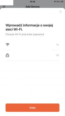
    App screen with a Wi-Fi information input form.
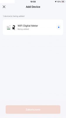
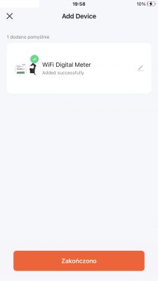
    Pairing:
    Mobile app screen showing the addition of a WiFi Digital Meter. App screen for adding a device with WiFi Digital Meter successfully added.
    After all, we are greeted by a rather unusual and modest panel. Strangely enough without a relay:
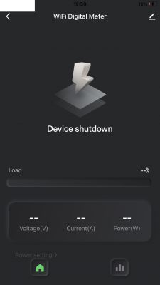
    App screen of WiFi Digital Meter indicating device shutdown
    The panel shows measurements of power, current and voltage:
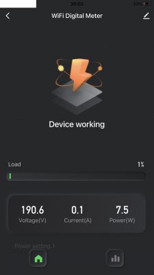
    WiFi digital meter app screen displaying voltage 190.6V, current 0.1A, and power 7.5W.
    But I don't need to post the communication here, as it has already been captured in a related topic:
    https://www.elektroda.com/rtvforum/topic3946128.html


    Uploading OpenBeken
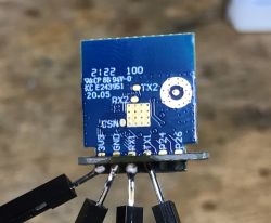
    The UART1 port is used both for programming and for communication with the MCU, so the WiFi module has to be soldered out:
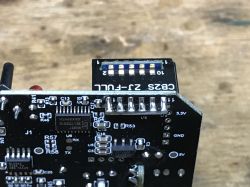
    Close-up of a PCB with a CB2S module and electronic components. Close-up of a circuit board with visible electronic components. Circuit board of a power meter with CB2S module next to it
    We solder the power supply, RX and TX, according to the instructions of our flasher:
    https://github.com/openshwprojects/BK7231GUIFlashTool
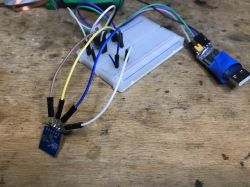
    Close-up of an electronic module connected to a breadboard with colored wires. Electronic module with visible connections and components.
    Flasher will not discover the configuration of this device, as it is based on TuyaMCU. We need to write an autoexec.bat where we map the dpID from the TuyaMCU to the OBK channels. Searching for the dpID is mentioned in related topics, although here I used tuyaMcu_sendQueryState , and more precisely I manually sent the same package ( uartSendHex 55AA0008000007 ):
    Info:MAIN:Time 152, idle 193677/s, free 73136, MQTT 0(9), bWifi 1, secondsWithNoPing 1, socks 2/38 
    Info:CMD:[WebApp Cmd 'uartSendHex 55AA0008000007' Result] OK
    Info:TuyaMCU:TUYAMCU received: 55 AA 03 07 00 08 12 02 00 04 00 00 00 4D 76 
    Info:TuyaMCU:TuyaMCU_ProcessIncoming[ver=3]: processing command 7 (State) with 15 bytes
    Info:TuyaMCU:TuyaMCU_ParseStateMessage: processing dpId 18, dataType 2-DP_TYPE_VALUE and 4 data bytes
    Info:TuyaMCU:TuyaMCU_ParseStateMessage: raw data 4 int: 77
    Info:TuyaMCU:TUYAMCU received: 55 AA 03 07 00 08 13 02 00 04 00 00 00 B1 DB 
    Info:TuyaMCU:TuyaMCU_ProcessIncoming[ver=3]: processing command 7 (State) with 15 bytes
    Info:TuyaMCU:TuyaMCU_ParseStateMessage: processing dpId 19, dataType 2-DP_TYPE_VALUE and 4 data bytes
    Info:TuyaMCU:TuyaMCU_ParseStateMessage: raw data 4 int: 177
    Info:TuyaMCU:TUYAMCU received: 55 AA 03 07 00 08 14 02 00 04 00 00 09 63 97 
    Info:TuyaMCU:TuyaMCU_ProcessIncoming[ver=3]: processing command 7 (State) with 15 bytes
    Info:TuyaMCU:TuyaMCU_ParseStateMessage: processing dpId 20, dataType 2-DP_TYPE_VALUE and 4 data bytes
    Info:TuyaMCU:TuyaMCU_ParseStateMessage: raw data 4 int: 2403
    Info:TuyaMCU:TUYAMCU received: 55 AA 03 00 00 01 01 04 
    Info:TuyaMCU:TuyaMCU_ProcessIncoming[ver=3]: processing command 0 (Hearbeat) with 8 bytes
    

    From the above log you can read out what dpIDs (data identifiers) with types and values were sent to us by the MCU. That's how I know that dpID 18 has a value of 77 (probably current), dpID 19 177 (power?) and dpID 20 is 2403 (here we know in advance that voltage). Just need to select the multipliers and map this to the channels in the OBK...
    So I wrote a script:
    
    startDriver TuyaMCU
    tuyaMCU_setBaudRate 115200
    tuyaMcu_defWiFiState 4
    
    // request full state from time to time (every 10 seconds, -1 repeats - forever)
    addRepeatingEvent 10 -1 uartSendHex 55AA0008000007
    
    // dpID 20 is voltage * 0.1
    setChannelType 1 Voltage_div10
    linkTuyaMCUOutputToChannel 20 val 1
    
    // dpID 18 is current * 0.001
    setChannelType 2 Current_Div1000
    linkTuyaMCUOutputToChannel 18 val 2
    
    // dpID 19 is power * 0.1
    setChannelType 3 Power_Div10
    linkTuyaMCUOutputToChannel 19 val 3


    The above script creates three channels (power, current and voltage), maps the dpID from the TuyaMCU to these channels, additionally forces a WiFi state of 0x04 (we simulate a connection to the cloud) and additionally periodically sends a state refresh request to provide us with the most recent measurements.
    Result:
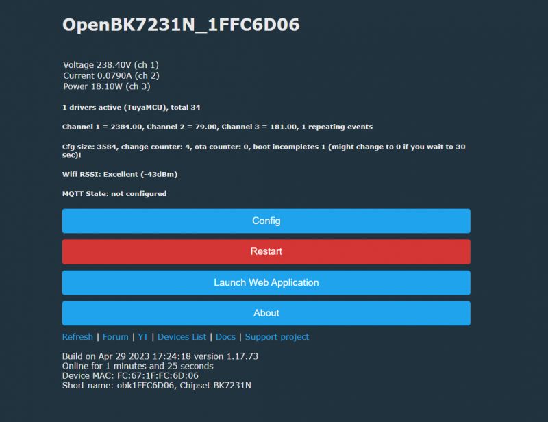
    Screenshot of the OpenBK7231N control panel.
    NOTE - without default WiFi state 0x04, at first the LED on the device was red and then flashing, but the device would not give measurements. After setting the default WiFi state to 0x04 this diode went off and the measurements appeared.
    This is a sample log from the OpenBeken Web App, it also shows the received dpID:
    
    
    bT obk1FFC6D06/+/set
    Info:MQTT:MQTT_RegisterCallback called for bT bekens/ subT bekens/+/set
    Info:MQTT:MQTT_RegisterCallback called for bT cmnd/obk1FFC6D06/ subT cmnd/obk1FFC6D06/+
    Info:MQTT:MQTT_RegisterCallback called for bT cmnd/bekens/ subT cmnd/bekens/+
    Info:MQTT:MQTT_RegisterCallback called for bT obk1FFC6D06/ subT obk1FFC6D06/+/get
    Info:CMD:CMD_StartScript: started autoexec.bat at the beginning
    Info:MAIN:Main_Init_After_Delay done
    Info:MAIN:Started TuyaMCU.
    Info:MAIN:Time 1, idle 276756/s, free 78120, MQTT 0(0), bWifi 0, secondsWithNoPing -1, socks 2/38 
    Info:TuyaMCU:TUYAMCU received: 55 AA 03 00 00 01 01 04 
    Info:TuyaMCU:TuyaMCU_ProcessIncoming[ver=3]: processing command 0 (Hearbeat) with 8 bytes
    Info:MAIN:Time 2, idle 466680/s, free 78120, MQTT 0(0), bWifi 0, secondsWithNoPing -1, socks 2/38 
    Info:TuyaMCU:TUYAMCU received: 55 AA 03 01 00 2A 7B 22 70 22 3A 22 64 6A 66 65 70 39 73 36 73 33 62 32 71 6B 38 39 22 2C 22 76 22 3A 22 31 2E 30 2E 30 22 2C 22 6D 22 3A 32 7D 63 
    Info:TuyaMCU:TuyaMCU_ProcessIncoming[ver=3]: processing command 1 (QueryProductInformation) with 49 bytes
    Info:TuyaMCU:TuyaMCU_ParseQueryProductInformation: received {"p":"djfep9s6s3b2qk89","v":"1.0.0","m":2}
    Info:MAIN:Time 3, idle 186861/s, free 78120, MQTT 0(0), bWifi 0, secondsWithNoPing -1, socks 2/38 
    Info:TuyaMCU:TUYAMCU received: 55 AA 03 02 00 00 04 
    Info:TuyaMCU:TuyaMCU_ProcessIncoming[ver=3]: processing command 2 (MCUconf) with 7 bytes
    Info:TuyaMCU:TuyaMCU_ProcessIncoming: TUYA_CMD_MCU_CONF, TODO!
    Info:MAIN:Time 4, idle 181710/s, free 78120, MQTT 0(0), bWifi 0, secondsWithNoPing -1, socks 2/38 
    Info:TuyaMCU:TUYAMCU received: 55 AA 03 07 00 08 12 02 00 04 00 00 00 4B 74 
    Info:TuyaMCU:TuyaMCU_ProcessIncoming[ver=3]: processing command 7 (State) with 15 bytes
    Info:TuyaMCU:TuyaMCU_ParseStateMessage: processing dpId 18, dataType 2-DP_TYPE_VALUE and 4 data bytes
    Info:TuyaMCU:TuyaMCU_ParseStateMessage: raw data 4 int: 75
    Info:TuyaMCU:TUYAMCU received: 55 AA 03 07 00 08 13 02 00 04 00 00 00 AF D9 
    Info:TuyaMCU:TuyaMCU_ProcessIncoming[ver=3]: processing command 7 (State) with 15 bytes
    Info:TuyaMCU:TuyaMCU_ParseStateMessage: processing dpId 19, dataType 2-DP_TYPE_VALUE and 4 data bytes
    Info:TuyaMCU:TuyaMCU_ParseStateMessage: raw data 4 int: 175
    Info:TuyaMCU:TUYAMCU received: 55 AA 03 07 00 08 14 02 00 04 00 00 09 55 89 
    Info:TuyaMCU:TuyaMCU_ProcessIncoming[ver=3]: processing command 7 (State) with 15 bytes
    Info:TuyaMCU:TuyaMCU_ParseStateMessage: processing dpId 20, dataType 2-DP_TYPE_VALUE and 4 data bytes
    Info:TuyaMCU:TuyaMCU_ParseStateMessage: raw data 4 int: 2389
    Info:MAIN:Time 5, idle 187156/s, free 78120, MQTT 0(0), bWifi 0, secondsWithNoPing -1, socks 2/38 
    Info:MAIN:ssid:ELEKTRODA_WIFI key:REDACTED
    Info:TuyaMCU:TUYAMCU received: 55 AA 03 00 00 01 01 04 
    Info:TuyaMCU:TuyaMCU_ProcessIncoming[ver=3]: processing command 0 (Hearbeat) with 8 bytes
    Info:MAIN:Time 6, idle 161327/s, free 72656, MQTT 0(0), bWifi 0, secondsWithNoPing -1, socks 2/38 
    Info:MAIN:Boot complete time reached (5 seconds)
    Info:CFG:####### Set Boot Complete #######
    Info:TuyaMCU:TUYAMCU received: 55 AA 03 03 00 00 05 
    Info:TuyaMCU:TuyaMCU_ProcessIncoming[ver=3]: processing command 3 (WiFiState) with 7 bytes
    Info:MAIN:Time 7, idle 174407/s, free 72656, MQTT 0(0), bWifi 0, secondsWithNoPing -1, socks 2/38 
    Info:MAIN:Time 8, idle 87090/s, free 72760, MQTT 0(0), bWifi 0, secondsWithNoPing -1, socks 2/38 
    Info:MAIN:Time 9, idle 0/s, free 72760, MQTT 0(0), bWifi 0, secondsWithNoPing -1, socks 2/38 
    Info:TuyaMCU:TUYAMCU received: 55 AA 03 00 00 01 01 04 
    Info:TuyaMCU:TuyaMCU_ProcessIncoming[ver=3]: processing command 0 (Hearbeat) with 8 bytes
    Info:MAIN:Time 10, idle 0/s, free 72760, MQTT 0(0), bWifi 0, secondsWithNoPing -1, socks 2/38 
    Info:GEN:dhcp=0 ip=0.0.0.0 gate=0.0.0.0 mask=0.0.0.0 mac=fc:67:1f:fc:6d:06 
    Info:GEN:sta: 0, softap: 0, b/g/n
    Info:MAIN:Main_OnWiFiStatusChange - WIFI_STA_CONNECTING - 1
    Info:MAIN:Main_OnWiFiStatusChange - WIFI_STA_CONNECTED - 4
    Info:MAIN:Main_OnWiFiStatusChange - WIFI_STA_CONNECTED - 4
    Info:MAIN:Time 11, idle 88454/s, free 73088, MQTT 0(0), bWifi 1, secondsWithNoPing -1, socks 2/38 
    Info:MAIN:Time 12, idle 183454/s, free 72912, MQTT 0(0), bWifi 1, secondsWithNoPing -1, socks 3/38 
    Info:MQTT:mqtt_host empty, not starting mqtt
    Info:MAIN:Time 13, idle 192457/s, free 73128, MQTT 0(1), bWifi 1, secondsWithNoPing -1, socks 2/38 
    Info:TuyaMCU:TUYAMCU received: 55 AA 03 00 00 01 01 04 
    Info:TuyaMCU:TuyaMCU_ProcessIncoming[ver=3]: processing command 0 (Hearbeat) with 8 bytes
    Info:TuyaMCU:TUYAMCU received: 55 AA 03 07 00 08 13 02 00 04 00 00 00 B4 DE 
    Info:TuyaMCU:TuyaMCU_ProcessIncoming[ver=3]: processing command 7 (State) with 15 bytes
    Info:TuyaMCU:TuyaMCU_ParseStateMessage: processing dpId 19, dataType 2-DP_TYPE_VALUE and 4 data bytes
    Info:TuyaMCU:TuyaMCU_ParseStateMessage: raw data 4 int: 180
    Info:MAIN:Time 14, idle 190254/s, free 73128, MQTT 0(1), bWifi 1, secondsWithNoPing -1, socks 2/38 
    Info:MAIN:Time 15, idle 181946/s, free 73128, MQTT 0(1), bWifi 1, secondsWithNoPing -1, socks 2/38 
    Info:MAIN:Time 16, idle 189477/s, free 73128, MQTT 0(1), bWifi 1, secondsWithNoPing -1, socks 2/38 
    Info:MAIN:Time 17, idle 189969/s, free 73128, MQTT 0(1), bWifi 1, secondsWithNoPing -1, socks 2/38 
    Info:TuyaMCU:TUYAMCU received: 55 AA 03 00 00 01 01 04 
    Info:TuyaMCU:TuyaMCU_ProcessIncoming[ver=3]: processing command 0 (Hearbeat) with 8 bytes
    Info:MAIN:Time 18, idle 185606/s, free 73128, MQTT 0(1), bWifi 1, secondsWithNoPing -1, socks 2/38 
    Info:MAIN:Time 19, idle 187869/s, free 73128, MQTT 0(1), bWifi 1, secondsWithNoPing -1, socks 2/38 
    Info:MAIN:Time 20, idle 188410/s, free 73128, MQTT 0(1), bWifi 1, secondsWithNoPing -1, socks 2/38 
    Info:GEN:dhcp=0 ip=192.168.0.161 gate=192.168.0.1 mask=255.255.255.0 mac=fc:67:1f:fc:6d:06 
    Info:GEN:sta: 1, softap: 0, b/g/n
    Info:GEN:sta:rssi=-46,ssid=ELEKTRODA_WIFI,bssid=28:87:ba:a0:f5:6d ,channel=3,cipher_type:CCMP
    Info:MAIN:Time 21, idle 194897/s, free 73128, MQTT 0(1), bWifi 1, secondsWithNoPing -1, socks 2/38 
    Info:TuyaMCU:TUYAMCU received: 55 AA 03 00 00 01 01 04 
    Info:TuyaMCU:TuyaMCU_ProcessIncoming[ver=3]: processing command 0 (Hearbeat) with 8 bytes
    Info:MAIN:Time 22, idle 197878/s, free 72912, MQTT 0(1), bWifi 1, secondsWithNoPing -1, socks 3/38 
    Info:MAIN:Time 23, idle 188471/s, free 73128, MQTT 0(1), bWifi 1, secondsWithNoPing -1, socks 2/38 
    Info:MAIN:Time 24, idle 186461/s, free 73128, MQTT 0(1), bWifi 1, secondsWithNoPing -1, socks 2/38 
    Info:MAIN:Time 25, idle 189066/s, free 73128, MQTT 0(1), bWifi 1, secondsWithNoPing -1, socks 2/38 
    Info:TuyaMCU:TUYAMCU received: 55 AA 03 00 00 01 01 04 
    Info:TuyaMCU:TuyaMCU_ProcessIncoming[ver=3]: processing command 0 (Hearbeat) with 8 bytes
    Info:MAIN:Time 26, idle 190211/s, free 73128, MQTT 0(1), bWifi 1, secondsWithNoPing -1, socks 2/38 
    

    Additionally it is worth running the TuyaMCU queue in flags and adding to autoexec.bat powersave 1 .

    Summary
    After changing the firmware and uploading my autoexec.bat you can already pair this device with Home Assistant via automatic Discovery in OBK . The whole thing already works locally, without the cloud.
    The device works satisfactorily, but could at least show a bit more data. I couldn't find any more interesting dpIDs, the device doesn't report anything else.
    You could consider trying to rewire BL0942 directly to the WiFi module, the MCU would then have to be removed. This would also allow for self-calibration already in the OBK itself, but it's hard for me to even determine if this is a plus or minus - the factory calibration isn't that bad, although I haven't done any comparative measurements in this particular case.

    Cool? Ranking DIY
    Helpful post? Buy me a coffee.
    About Author
    p.kaczmarek2
    Moderator Smart Home
    Offline 
    p.kaczmarek2 wrote 11906 posts with rating 9978, helped 571 times. Been with us since 2014 year.
  • ADVERTISEMENT
  • #2 21078268
    gregor_pn
    Level 16  
    Hey, very cool topic solved.
    I have a question regarding just changing from Tuya to OBK. I have TO-Q-SY2-JWT and the change to OpenBeken comes out very nicely, works correctly, shows voltages, amperage and everything as it should however I noticed that one diode and one transistor in the circuit after the change to OBK started to heat up terribly - up to pomad 95oC. With the Tuya insertion this does not happen. Do you have any idea what could be wrong with this? Where to look? Ofc google didn't help, for "new" equipment.
  • ADVERTISEMENT
  • #3 21078277
    p.kaczmarek2
    Moderator Smart Home
    In what circuit are these elements
    There are two possibilities. Either you are simply missing powerSave 1 in autoexec.bat, i.e. dynamic sleep, power saving, or something on the GPIO is wrong.
    If powersave doesn't help, then check with a multimeter on which GPIO of the WiFi module this diode and transistor are. Maybe it needs to be set to AlwaysLow or AlwaysHigh....
    Helpful post? Buy me a coffee.
  • #4 21078487
    gregor_pn
    Level 16  
    You were right. PowerSave 1 doesn't solve the problem but looking after the GPIO was good advice. This particular switch has a bistable relay controlled by GPIO 24 and 26 alternating + o - depending on what state you want. I had a setup with something that held the state by holding power on that input and that's where the problem came from.

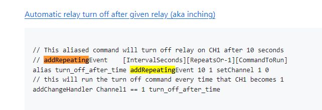
    I now have a question - if you know the solution that would be great. How do you solve this? How to force it to just give a pulse to the corresponding GPIO after pressing a button (software from the menu too) for a while?

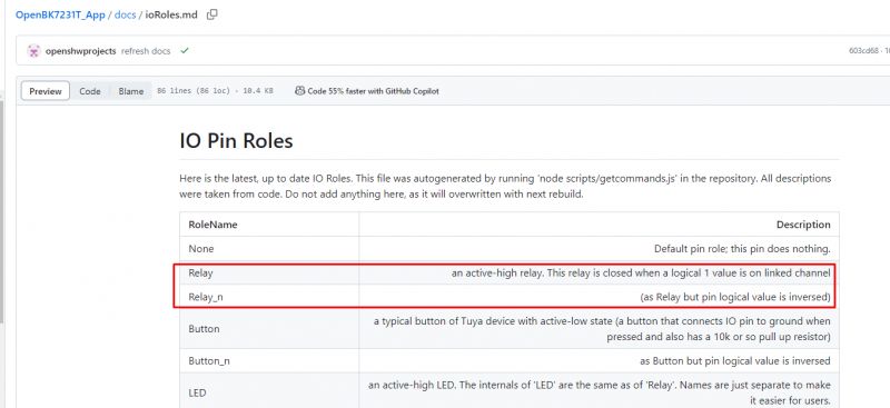
    There is a lot of information about this project but for example when I wanted to find a description what is the difference between Rel and Rel_n it.... well I had to guess what the author meant. ;) .
  • #5 21078532
    p.kaczmarek2
    Moderator Smart Home
    gregor_pn wrote:
    In this particular switch is a bistable relay controlled by GPIO 24 and 26 alternating + o - depending on what state you want. I had a configuration with something that held the state by holding power on this input and hence the problem.

    There is a driver for this:
    https://github.com/openshwprojects/OpenBK7231T_App/blob/main/docs/drivers.md
    Fragment of a table highlighting the Bridge option related to a relay driver.

    The appropriate GPIO roles must be set:
    https://github.com/openshwprojects/OpenBK7231T_App/blob/main/docs/ioRoles.md

    Fragment of documentation with a list of GPIO roles and their descriptions.


    gregor_pn wrote:
    How to force it to momentarily just give a pulse to the corresponding GPIO when a button is pressed (programmatically from the menu too)?

    If you want to script manually then you have examples here;
    https://github.com/openshwprojects/OpenBK7231T_App/blob/main/docs/autoexecExamples.md

    Screenshot with an example script for automatically turning off a relay after a specified time.

    gregor_pn wrote:

    what the difference between Rel and Rel_n is.... well I had to guess what the author meant. ;)

    The explanation is here:
    https://github.com/openshwprojects/OpenBK7231T_App/blob/main/docs/ioRoles.md

    Screenshot showing GPIO pin roles documentation in OpenBK7231T.


    By the way, since you have a device with a bistable relay, can you show me the JSON Tuya from that device? Instructions: https://www.youtube.com/watch?v=WunlqIMAdgw&ab_channel=Elektrodacom
    Helpful post? Buy me a coffee.
  • #6 21078587
    gregor_pn
    Level 16  
    I admire your wealth of knowledge
    Both ways I just tested and they worked. Brilliant.
    What about Tuya's JSON from the device it unfortunately went "in the sewer" because as you can see I'm not the smartest.... I have a copy of the flash.
    But I'm going to order a few more pieces now so when I change the software I'll toss you everything I have.
    By the way the device is made very nicely and thoughtfully.
  • #7 21078653
    p.kaczmarek2
    Moderator Smart Home
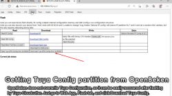
    But wait, after all, Tuya's JSON is not lost after uploading the firmware. He is there all the time, even after uploading OpenBeken. Unless you performed on chip erase all ?
    Helpful post? Buy me a coffee.
  • ADVERTISEMENT
  • #8 21078689
    gregor_pn
    Level 16  
    If you can tell me how to download it I will be happy to do so.
    I have not done EraseAll
  • #9 21078739
    p.kaczmarek2
    Moderator Smart Home
    p.kaczmarek2 wrote:
    can you show me the JSON of Tuya from this device? Instructions: https://www.youtube.com/watch?v=WunlqIMAdgw&ab_channel=Elektrodacom
    OpenBeken software interface for configuring LED RGB settings. Screenshot of the OpenBeken panel showing the Flash section with an option to download Tuya config. .
    Helpful post? Buy me a coffee.
  • ADVERTISEMENT
  • #11 21080257
    p.kaczmarek2
    Moderator Smart Home
    As far as I can see, however, the automatic detection of GPIO roles from my flasher managed it:
    
    Device configuration, as extracted from Tuya: 
    - Button (channel 1) on P17
    - LED (channel 1) on P9
    - Bridge Relay On (channel 1) on P24
    - Bridge Relay Off (channel 1) on P26
    - WiFi LED on P15
    Device seems to be using CBU module, which is using BK7231N.
    And the Tuya section starts at UNCOMMON POSITION 0
    

    so if we performed this at the beginning we would know that here is a bridge relay
    Helpful post? Buy me a coffee.
  • #12 21080264
    gregor_pn
    Level 16  
    This is your flasher? I'm full of admiration
    But I'll admit I'm not sure it is. The file seems to me to have looked different at the time of the flashing process itself. I'm not 100% sure but I'll confirm when I have fresh devices to make - they are already flowing to me.
  • #13 21080269
    p.kaczmarek2
    Moderator Smart Home
    Make a topic for each device you have, I will help with getting them up and running. We are creating list of devices here:
    https://openbekeniot.github.io/webapp/devicesList.html
    We already have 570 entries, we want to get to 600. I think I have to add there TO-Q-SY2-JWT....

    Flasher is my creation, here you have history of its creation:
    https://github.com/openshwprojects/BK7231GUIFlashTool/commits/main/

    Flasher detects GPIO roles based on Tuya configuration which is in the device already at the moment of uploading OpenBeken, so this configuration was 100% in your device from the beginning, so it's always worth to check it, because it can save some time. OpenBeken doesn't contain code that would move this configuration at all, so what is there in the flash is there from the beginning.

    The only thing to watch out for is that older versions of the flasher may not detect all roles correctly, I keep adding things there
    Helpful post? Buy me a coffee.
  • #14 21203940
    adrianpanella
    Level 4  
    >>21078268 Hi, where you able to determine the metering chip?
    Mine has no label on top. I'm curious if it is the same as de SY1. The SY2 is advertised as having over/under voltage protection and over current protection.
    Where you able to configure that too?

    It also has a temperature meassure. Could you make it work? from the json it seams to be in pin 28:
    "temp_mea_pin":"28",
  • #15 21204573
    p.kaczmarek2
    Moderator Smart Home
    Hello, where did you get temp_mea_pin key? Can you post full set of images and full JSON?
    There are no other mentions of temp_mea_pin on our forum yet.
    https://www.elektroda.com/rtvforum/find.php?q=temp_mea_pin
    Helpful post? Buy me a coffee.
  • #16 21205202
    adrianpanella
    Level 4  
    It was not actually mentioned in a post, but it is in the JSON file sent by @gregor_pn a couple of posts above.

    I have a device, but chips have no markings on top, so I couldn’t find much.

    But clearly SY2 is advertised as having temperature sensor.

    I also don’t know what is the energy meter chip and how this is different from SY1 in order to have the advertised voltage/current protection. Or is it purely firmware?
  • #17 21205336
    divadiow
    Level 34  
    >>21080130

    yes, interesting

    Code: Text
    Log in, to see the code
  • #18 21205358
    p.kaczmarek2
    Moderator Smart Home
    So what is connected to P28?
    https://www.elektroda.com/rtvforum/topic3951016.html#gallery-2

    Wait a sec, but this device has CB2S as in first post? So P28 is not routed? Huh.
    Helpful post? Buy me a coffee.
  • #19 21206481
    adrianpanella
    Level 4  
    This device I’m referring to is a TO-Q-SY2-JWT and has a CBU module.
    It was mention in the thread but is not the same as the first post.
    But this is the only thread I found (in any forum) that mentions the device.

    I believe it to be very similar to the SY1 which has the following mapping:
    ```
    ## P17: sensor button
    ## P15: blue led - status
    ## P9: red led - relay
    ## P24: on_signal
    ## P26: off_signal
    ## uart1: bl0942 energy meter
    ```

    And P28 presumably is connected to the temperature sensor that this versions adds over SY1.
    I’m not sure about bl0942 though.
    Those are my questions to @gregor_pn who apparently flashed it and made it work.
  • #20 21546734
    ghimpe--
    Level 10  
    Hello!
    I have a PJ-1103 and i managed to screw it up. Maybe you can help me recover it.
    First I made a backup of the original tuya firmware using your nice software flasher.
    Then I flashed the latest openbk firmware, then I manually ("Execute custom command" menu) run each line of code from your script. Because I then got weird values reported, (only the voltage was accurate, current/power was wrong, showing about 380W with no sensor connected) I decided to flash back the original firmware. It was then the moment I realized I screw something up. Even with the original firmware it would show weird values.

    Now I have on it openbk firmware but only the voltage reading is correct. The current stay at a fixed 90.0000A ! (current sensor is connected)

    Is there a change to repair this device?

    PS: I'm a newbie at this.
  • #21 21546985
    p.kaczmarek2
    Moderator Smart Home
    The script should be put in autoexec.bat , not just ran once via command line. If you ran it via commandline and reboot, then it won't run again after reboot. It has to be in autoexec.bat, because autoexec.bat is automatically run after each reboot. So, for a start, please try putting our script in autoexec.bat, then save, then do full power off and power on, and then check how your device behaves.

    You should also see TuyaMCU driver running in the main device page.
    Helpful post? Buy me a coffee.
  • #22 21546994
    ghimpe--
    Level 10  
    Hello mister p.kaczmarek2.
    Thank for your reply. I forgot to mention that at this time I have the script in autoexec.bat

    this is in my script:
    
    PowerSave 1
    startDriver TuyaMCU
    tuyaMCU_setBaudRate 115200
    tuyaMcu_defWiFiState 4
    
    // request full state from time to time (every 10 seconds, -1 repeats - forever)
    addRepeatingEvent 10 -1 uartSendHex 55AA0008000007
    
    // dpID 20 is voltage * 0.1
    setChannelType 1 Voltage_div10
    linkTuyaMCUOutputToChannel 20 val 1
    
    // dpID 18 is current * 0.00001
    setChannelType 2 Current_Div1000
    linkTuyaMCUOutputToChannel 18 val 2
    
    // dpID 19 is power * 0.1
    setChannelType 3 Power_Div10
    linkTuyaMCUOutputToChannel 19 val 3


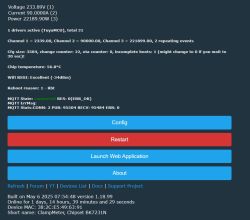
    This is the homepage of the device:


    Control panel of a ClampMeter device showing voltage, current, and power measurements.
  • #23 21547016
    p.kaczmarek2
    Moderator Smart Home
    So probably your piece has different dpIDs for current and power. You need to connect a known load, like 60W bulb, and then use tuyaMcu_sendQueryState to query all dpIDs, and then manually check each value and guess which dpID may be current, which may be power, etc.
    Helpful post? Buy me a coffee.
  • #24 21547030
    ghimpe--
    Level 10  
    Run the command and i got in the logs the same ID's.

    
    Info:TuyaMCU:ParseState: id 20 type 2-val len 4
    Info:TuyaMCU:ParseState: int32 2350
    Info:TuyaMCU:ParseState: id 18 type 2-val len 4
    Info:TuyaMCU:ParseState: int32 90000
    Info:TuyaMCU:ParseState: id 19 type 2-val len 4
    Info:TuyaMCU:ParseState: int32 223057


    I don't think the problem is related with openbeken, I think I screw up something in the device config in tuya mcu. It does't work even if I put back the original firmware.
  • #25 21547033
    p.kaczmarek2
    Moderator Smart Home
    And there is no more dpIDs?


    Well, if something is wrong with MCU, you can desolder MCU and connect BL0942 directly to WiFi module UART. Is your piece still using BL0942?
    Helpful post? Buy me a coffee.
  • #26 21547041
    ghimpe--
    Level 10  
    I think it uses BL0942 but will have to check to be sure when I get at home.

    Could it be that I am doing something wrong when I'm putting back the backup firmware? Is this normal to screw up just by flashing openbeken and then the original firmware back? Especially since I understand that the config is in the tuya mcu and not in the C2BS module?
  • #27 21547043
    p.kaczmarek2
    Moderator Smart Home
    No, I never seen such issue before. You can't really affect the MCU firmware with WiFi firmware. The only scenario I can imagine is when you change some setting in Tuya App, like, I don't know, change calibration, and then flash OBK and forget the calibration dpID , so you are no longer able to calibrate. But that's still fixable if you flash back Tuya firmware.
    Helpful post? Buy me a coffee.
  • #28 21547051
    ghimpe--
    Level 10  
    Do you somehow still have the original copy of the firmware? Maybe my backup is corrupt and I am willing to test with your backup.
  • #29 21547982
    p.kaczmarek2
    Moderator Smart Home
    PJ-MGW1103, as read on 2023.04.29
    Helpful post? Buy me a coffee.
  • #30 21548050
    ghimpe--
    Level 10  
    Thank you, will try as soon as I can.

    If I would go to the hardware modification route, what should I do exactly? It's as simple as removing the tuya mcu chip and then just wire tx/rx pins from the BL0942 chip to the CB2S rx/tx pins?

Topic summary

The discussion revolves around freeing the PJ-MGW1103 energy meter from the Tuya ecosystem and connecting it to Home Assistant using OpenBeken firmware. Users share experiences with the TuyaMCU protocol, the BK7231N WiFi module, and the challenges faced during the transition. Issues such as overheating components after flashing OpenBeken, GPIO configuration, and the extraction of JSON data from the device are addressed. Solutions include setting GPIO roles correctly, using power-saving commands, and utilizing available drivers for bistable relay control. Participants also inquire about the metering chip and temperature sensor integration, comparing the device to similar models like the TO-Q-SY2-JWT and SY1.
Summary generated by the language model.
ADVERTISEMENT